Toyota Corolla Cross: Washer Fluid Level Warning Switch Circuit
DESCRIPTION
When the washer fluid level is lower than a certain level, a warning message is displayed on the combination meter assembly.
WIRING DIAGRAM
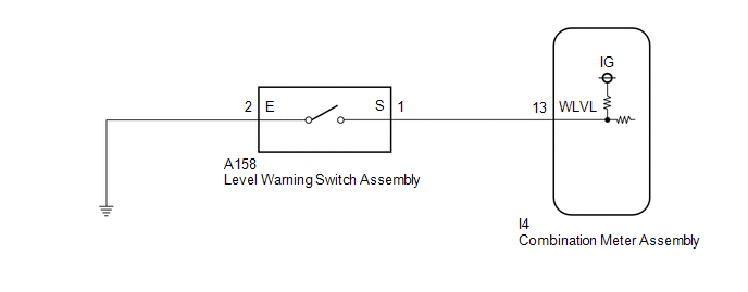
PROCEDURE
| 1. |
READ VALUE USING GTS (COMBINATION METER) |
(a) Read the Data List according to the display on the GTS.
Body Electrical > Combination Meter > Data List|
Tester Display | Measurement Item |
Range | Normal Condition |
Diagnostic Note |
|---|---|---|---|---|
|
Washer Level Warning Switch |
Washer fluid level warning switch |
OFF or ON | OFF: Washer fluid level not low ON: Washer fluid level low |
- |
|
Tester Display |
|---|
| Washer Level Warning Switch |
OK:
The GTS display changes correctly in response to the washer fluid level.
| OK | .gif) | REPLACE COMBINATION METER ASSEMBLY |
|
.gif)
| 2. |
INSPECT LEVEL WARNING SWITCH ASSEMBLY |
HINT:
This check should be performed with the level warning switch assembly installed on the washer jar.
(a) Remove the level warning switch assembly.
| (b) Fill the washer jar with washer fluid. |
|
(c) Measure the resistance according to the value(s) in the table below.
Standard Resistance:
|
Tester Connection | Condition |
Specified Condition |
|---|---|---|
|
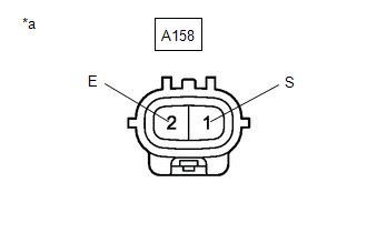
A158-1 (S) - A158-2 (E) |
Fluid volume is 600 to 800 cc (36.6 to 48.8 cu.in.) or higher* |
10 kΩ or higher |
|
Fluid volume is 600 to 800 cc (36.6 to 48.8 cu.in.) or lower* |
Below 1 Ω |
HINT:
*: The level warning switch assembly begins operating when the fluid volume is 600 to 800 cc (36.6 to 48.8 cu.in.) depending on the vehicle condition.
| NG | | REPLACE LEVEL WARNING SWITCH ASSEMBLY |
|
| 3. |
CHECK HARNESS AND CONNECTOR (LEVEL WARNING SWITCH ASSEMBLY - COMBINATION METER ASSEMBLY) |
(a) Disconnect the I4 combination meter assembly connector.
(b) Measure the resistance according to the value(s) in the table below.
Standard Resistance:
|
Tester Connection | Condition |
Specified Condition |
|---|---|---|
|
A158-1 (S) - I4-13 (WLVL) |
Always | Below 1 Ω |
|
A158-1 (S) or I4-13 (WLVL) - Body ground |
Always | 10 kΩ or higher |
| NG | | REPAIR OR REPLACE HARNESS OR CONNECTOR |
|
| 4. |
CHECK HARNESS AND CONNECTOR (LEVEL WARNING SWITCH ASSEMBLY - BODY GROUND) |
(a) Measure the resistance according to the value(s) in the table below.
Standard Resistance:
|
Tester Connection | Condition |
Specified Condition |
|---|---|---|
|
A158-2 (E) - Body ground |
Always | Below 1 Ω |
| OK | | REPLACE COMBINATION METER ASSEMBLY |
| NG | | REPAIR OR REPLACE HARNESS OR CONNECTOR |


