Toyota Corolla Cross: Removal
REMOVAL
CAUTION / NOTICE / HINT
COMPONENTS (REMOVAL)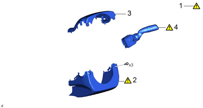
|
Procedure | Part Name Code |
.png) |
.png) |
 |
|---|---|---|---|---|---|
|
1 | STEERING WHEEL POSITION |
- |
|
- | - |
|
2 | LOWER STEERING COLUMN COVER |
45287 |
|
- | - |
|
3 | UPPER STEERING COLUMN COVER |
45286B | - |
- | - |
|
4 | WINDSHIELD WIPER SWITCH ASSEMBLY |
84650 |
|
- | - |
.gif)
PROCEDURE
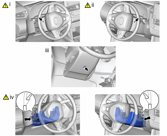
1. ADJUST STEERING WHEEL POSITION

.png) |
Lower |
.png) |
Extend |
(1) Adjust steering wheel position by the below procedure.
1. Release the tilt and telescopic lever and fully extend and lower the steering column sub-assembly.
2. Lock the tilt and telescopic lever.
2. REMOVE LOWER STEERING COLUMN COVER
|
|
NOTICE: Removing the lower steering column cover sub-assembly in the incorrect order will cause the parts to break. |
.png) |
Push Area |
|
Push |
(1) Turn the steering wheel assembly to the left to remove the screw.
(2) Turn the steering wheel assembly to the right to remove the screw.
(3) Remove the screw.
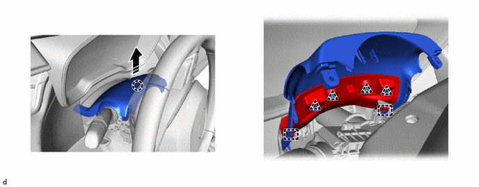
(4) Disengage the claws to remove the lower steering column cover as show in the illustration.
3. REMOVE UPPER STEERING COLUMN COVER
.png) |
Remove in this Direction |
- | - |
4. REMOVE WINDSHIELD WIPER SWITCH ASSEMBLY

|
|
Remove in this Direction |
- | - |
(1) Using a screwdriver with its tip wrapped with protective tape, disengage the claw to remove the windshield wiper switch assembly as shown in the illustration.
NOTICE:
If the claw is pulled with excessive force, it may break.


