Toyota Corolla Cross: Inspection
INSPECTION
PROCEDURE
1. INSPECT SIDE TURN SIGNAL LIGHT ASSEMBLY LH
(a) Check that the side turn signal light assembly LH.
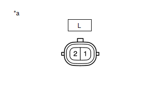
| (1) Apply auxiliary battery voltage to the side turn signal light assembly LH and check that the light comes on.
OK: |
Tester Connection | Specified Condition | |
L-2 - Auxiliary battery positive (+) L-1 - Auxiliary battery negative (-) |
Side turn signal light LH comes on |
If the result is not as specified, replace the side turn signal light assembly LH. |
 |
|
*a | Component without harness connected
(Side Turn Signal Light Assembly LH) | | |
2. INSPECT SIDE TURN SIGNAL LIGHT ASSEMBLY RH
(a) Check that the side turn signal light assembly RH.
| (1) Apply auxiliary battery voltage to the side turn signal light assembly RH and check that the light comes on.
OK: |
Tester Connection | Specified Condition | |
K-2 - Auxiliary battery positive (+) K-1 - Auxiliary battery negative (-) |
Side turn signal light RH comes on |
If the result is not as specified, replace the side turn signal light assembly RH. |
 |
|
*a | Component without harness connected
(Side Turn Signal Light Assembly RH) | | |
READ NEXT:
INSTALLATION CAUTION / NOTICE / HINT COMPONENTS (INSTALLATION)
Procedure Part Name Code
1 SIDE TURN SIGNAL LIGHT ASSEMBLY
81740 -
- -
2 OUTER MI
ON-VEHICLE INSPECTION PROCEDURE
1. INSPECT STOP LIGHT SWITCH ASSEMBLY (a) Disconnect the A53 stop light switch assembly connector.
(b) Measure the voltage and resistance on the wire harness side
SEE MORE:
DESCRIPTION In this circuit, the compressor with pulley assembly receives refrigerant compression demand signals from the air conditioning amplifier assembly.
Based on this signal, the compressor with pulley assembly changes the amount of compressor output.
DTC No. Detection Item
DTC
DTC SUMMARY MALFUNCTION DESCRIPTION These DTCs indicate that the resolver output signal is abnormal. The cause of this malfunction may be one of the following:
Area Main Malfunction Description
Inverter low-voltage circuit
The connectors are not connected properly
H


