Toyota Corolla Cross: On-vehicle Inspection
ON-VEHICLE INSPECTION
PROCEDURE
1. INSPECT STOP LIGHT SWITCH ASSEMBLY
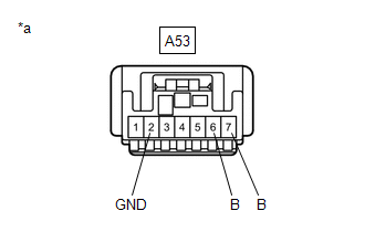
(a) Disconnect the A53 stop light switch assembly connector.
| (b) Measure the voltage and resistance on the wire harness side connector according to the value(s) in the table below.
Standard Voltage: |
Tester Connection | Condition |
Specified Condition | |
A53-7 (B) - A53-2 (GND) |
Always | 11 to 14 V | |
A53-6 (B) - A53-2 (GND) |
Ignition switch on (IG) |
11 to 14 V | Standard Resistance: |
Tester Connection | Condition |
Specified Condition | |
A53-2 (GND) - Body ground |
Always | Below 1 Ω |
If the result is not as specified, repair or replace the wire harness or connector. |
 |
|
*a | Front view of wire harness connector
(to Stop Light Switch Assembly) | | |
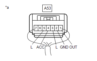
(c) Connect the A53 stop light switch assembly connector.
| (d) Measure the voltage according to the value(s) in the table below.
Standard Voltage: |
Tester Connection | Condition |
Specified Condition | |
A53-1 (OUT) - A53-2 (GND) |
Brake pedal not depressed |
Below 1 V | |
A53-1 (OUT) - A53-2 (GND) |
Brake pedal depressed |
11 to 14 V | |
A53-3 (L) - A53-2 (GND) |
Brake pedal not depressed |
Below 1 V | |
A53-3 (L) - A53-2 (GND) |
Brake pedal depressed |
11 to 14 V | |
A53-4 (ACC) - A53-2 (GND) |
Always | 11 to 14 V | |
A53-5 (L) - A53-2 (GND) |
Ignition switch on (IG), brake pedal not depressed |
11 to 14 V | |
A53-5 (L) - A53-2 (GND) |
Ignition switch on (IG), brake pedal depressed |
Below 1 V | If the result is not as specified, replace the stop light switch assembly. |
 |
|
*a | Component with harness connected
(Stop Light Switch Assembly) | | |
READ NEXT:
REMOVAL CAUTION / NOTICE / HINT COMPONENTS (REMOVAL)
Procedure Part Name Code
1 NO. 1 INSTRUMENT PANEL UNDER COVER SUB-ASSEMBLY
55606 -
- -
2 NO
INSTALLATION CAUTION / NOTICE / HINT COMPONENTS (INSTALLATION)
Procedure Part Name Code
1 STOP LIGHT SWITCH MOUNTING ADJUSTER
84345 -
- -
2 STOP
SEE MORE:
DESCRIPTION
Refer to DTC C050612
Click here
DTC No.
Detection Item
DTC Detection Condition
Trouble Area
C05061C
Right Front Wheel Speed Sensor Circuit Voltage Out
of Range
When the vehicle is being drive
TERMINALS OF ECU
REAR TELEVISION CAMERA ASSEMBLY
(a) Disconnect the rear television camera assembly connector.
(b) Measure the voltage on the wire harness side connector according
to the value(s) in the table below.
Terminal No. (Symbol)
Terminal Description


