Toyota Corolla Cross: Installation
INSTALLATION
CAUTION / NOTICE / HINT
COMPONENTS (INSTALLATION)
|
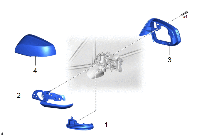
Procedure | Part Name Code |
|
|
|
|
1 | SIDE TURN SIGNAL LIGHT ASSEMBLY |
81740 | - |
- | - |
|
2 | OUTER MIRROR LOWER COVER |
- | - |
- | - |
|
3 | OUTER MIRROR BEZEL |
- | - |
- | - |
|
4 | OUTER MIRROR COVER |
87945 | - |
- | - |
CAUTION / NOTICE / HINT
HINT:
- Use the same procedure for the RH side and LH side.
- The following procedure is for the LH side.
PROCEDURE
1. INSTALL SIDE TURN SIGNAL LIGHT ASSEMBLY
2. INSTALL OUTER MIRROR LOWER COVER
3. INSTALL OUTER MIRROR BEZEL
4. INSTALL OUTER MIRROR COVER
Click here
READ NEXT:
ON-VEHICLE INSPECTION PROCEDURE
1. INSPECT STOP LIGHT SWITCH ASSEMBLY (a) Disconnect the A53 stop light switch assembly connector.
(b) Measure the voltage and resistance on the wire harness side
REMOVAL CAUTION / NOTICE / HINT COMPONENTS (REMOVAL)
Procedure Part Name Code
1 NO. 1 INSTRUMENT PANEL UNDER COVER SUB-ASSEMBLY
55606 -
- -
2 NO
SEE MORE:
FAIL-SAFE CHART
FAIL-SAFE FUNCTION
(a) If the system is malfunctioning, the telltale warning message
is displayed on the multi-information display and the system is suspended in accordance
with the malfunction.
Telltale Status List
Indicator Status
Conditions
DESCRIPTION The combination meter assembly receives the hazard warning signal switch assembly on signal and controls the operation of the hazard warning lights. WIRING DIAGRAM
CAUTION / NOTICE / HINT
NOTICE:
When replacing the combination meter assembly, always replace it with a new one. If a c