Toyota Corolla Cross: Removal
REMOVAL
CAUTION / NOTICE / HINT
COMPONENTS (REMOVAL)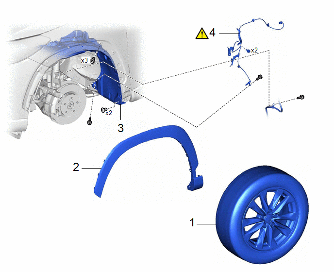
|
Procedure |
Part Name Code |
.png) |
.png) |
.png) |
|
|---|---|---|---|---|---|
|
1 |
FRONT WHEEL |
- |
- |
- |
- |
|
2 |
WHEEL OPENING MOULDING |
- |
- |
- |
- |
|
3 |
FRONT FENDER LINER |
53846A |
- |
- |
- |
|
4 |
FRONT SPEED SENSOR |
89543 |
|
- |
- |
CAUTION / NOTICE / HINT
HINT:
- Use the same procedure for the RH side and LH side.
- The following procedure is for the LH side.
- The front speed sensor rotor is a component of the front axle hub sub-assembly. If the front speed sensor rotor is malfunctioning, replace the front axle hub sub-assembly.
PROCEDURE
1. REMOVE FRONT WHEEL
Click here .gif)
2. REMOVE WHEEL OPENING MOULDING
Click here
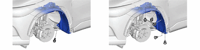
3. SEPARATE FRONT FENDER LINER
4. REMOVE FRONT SPEED SENSOR
(1) Turn back the front fender liner.
(2) Disconnect the connector.
(3) Disengage the clamp from the vehicle body.
(4) Disengage the clamp from the vehicle body.
(5) Remove the 2 bolts and separate the 2 front speed sensor clamps.
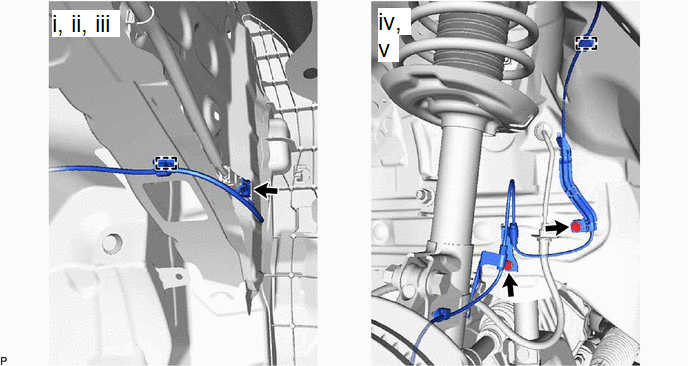
(1) Remove the bolt and separate the front flexible hose and front speed sensor clamp from the front shock absorber assembly.
(2) Disengage the clamp from the front shock absorber assembly.
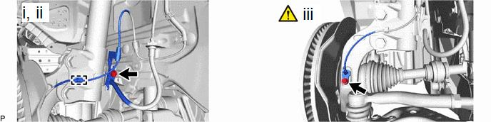
(3) Remove the bolt and front speed sensor from the steering knuckle.
NOTICE:
- Keep the tip of the front speed sensor and installation hole free of foreign matter.
- Do not rotate or apply excessive force to the front speed sensor when removing it from the steering knuckle. Rotating or applying excessive force may result in damage to the front speed sensor.


