
Toyota Corolla Cross: Installation
INSTALLATION
CAUTION / NOTICE / HINT
COMPONENTS (INSTALLATION)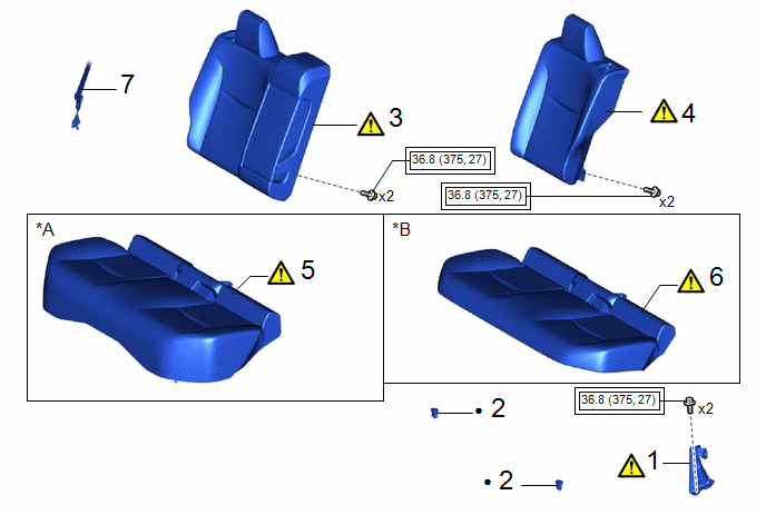
|
Procedure | Part Name Code |
.png) |
.png) |
 |
|---|---|---|---|---|---|
|
1 | REAR CENTER SEATBACK HINGE SUB-ASSEMBLY |
71305A |
|
- | - |
|
2 | REAR SEAT CUSHION LOCK HOOK |
72693 | - |
- | - |
|
3 | REAR SEATBACK ASSEMBLY RH |
- |
|
- | - |
|
4 | REAR SEATBACK ASSEMBLY LH |
- |
|
- | - |
|
5 | BENCH TYPE REAR SEAT CUSHION ASSEMBLY |
- |
|
- | - |
|
6 | BENCH TYPE REAR SEAT CUSHION ASSEMBLY |
- |
|
- | - |
|
7 | REAR CENTER SEAT OUTER BELT ASSEMBLY |
73350C | - |
- | - |
.gif)
|
*A | for Gasoline Model |
*B | for HEV Model |
.png) |
Tightening torque for "Major areas involving basic vehicle performance such as moving/turning/stopping" : N*m (kgf*cm, ft.*lbf) |
● | Non-reusable part |
CAUTION / NOTICE / HINT
CAUTION:
Wear protective gloves. Sharp areas on the parts may injure your hands.
.png)
PROCEDURE
1. INSTALL REAR CENTER SEATBACK HINGE SUB-ASSEMBLY
|
|
HINT: Perform this procedure only when replacement of the rear center seatback hinge sub-assembly is necessary. |
Torque:
36.8 N·m {375 kgf·cm, 27 ft·lbf}
2. INSTALL REAR SEAT CUSHION LOCK HOOK
3. INSTALL REAR SEATBACK ASSEMBLY RH
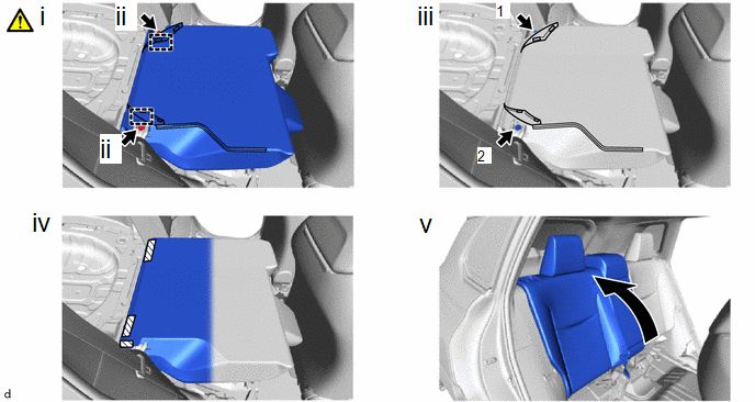
(1) Place the rear seatback assembly RH in the cabin.
NOTICE:
Be careful not to damage the vehicle body.
(2) Engage the guides to temporarily install the rear seatback assembly RH with the 2 bolts.
(3) Tighten the 2 bolts in the order shown in the illustration.
Torque:
36.8 N·m {375 kgf·cm, 27 ft·lbf}
(4) Engage the hook and loop fasteners.
(5) Return the rear seatback assembly RH.
4. INSTALL REAR SEATBACK ASSEMBLY LH
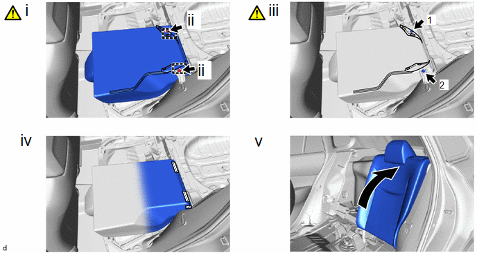
(1) Place the rear seatback assembly LH in the cabin.
NOTICE:
Be careful not to damage the vehicle body.
(2) Engage the guides to temporarily install the rear seatback assembly LH with the 2 bolts.
(3) Tighten the 2 bolts in the order shown in the illustration.
Torque:
36.8 N·m {375 kgf·cm, 27 ft·lbf}
(4) Engage the hook and loop fasteners.
(5) Return the rear seatback assembly LH.
5. INSTALL BENCH TYPE REAR SEAT CUSHION ASSEMBLY (for Gasoline Model)
|
|
NOTICE: Be careful not to damage the vehicle body. |
6. INSTALL BENCH TYPE REAR SEAT CUSHION ASSEMBLY (for HEV Model)
|
|
NOTICE: Be careful not to damage the vehicle body. |
7. CONNECT REAR CENTER SEAT OUTER BELT ASSEMBLY


