Toyota Corolla Cross: Installation
INSTALLATION
CAUTION / NOTICE / HINT
COMPONENTS (INSTALLATION)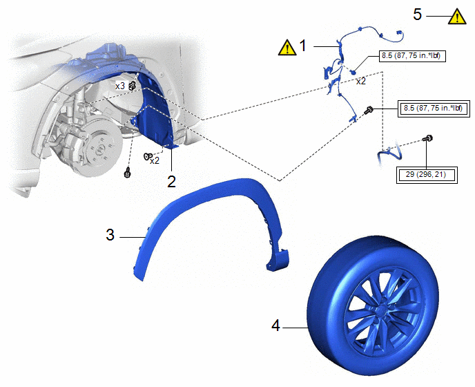
|
Procedure |
Part Name Code |
.png) |
.png) |
.png) |
|
|---|---|---|---|---|---|
|
1 |
FRONT SPEED SENSOR |
89543 |
|
- |
- |
|
2 |
FRONT FENDER LINER |
53876A |
- |
- |
- |
|
3 |
WHEEL OPENING MOULDING |
- |
- |
- |
- |
|
4 |
FRONT WHEEL |
- |
- |
- |
- |
|
5 |
CHECK FOR SPEED SENSOR SIGNAL |
- |
|
- |
- |
.png) |
Tightening torque for "Major areas involving basic vehicle performance such as moving/turning/stopping" : N*m (kgf*cm, ft.*lbf) |
.png) |
N*m (kgf*cm, ft.*lbf): Specified torque |
CAUTION / NOTICE / HINT
HINT:
- Use the same procedure for the RH side and LH side.
- The following procedure is for the LH side.
- The front speed sensor rotor is a component of the front axle hub sub-assembly. If the front speed sensor rotor is malfunctioning, replace the front axle hub sub-assembly.
PROCEDURE
1. INSTALL FRONT SPEED SENSOR
|
|
NOTICE: Do not twist the front speed sensor wire harness when installing it. |
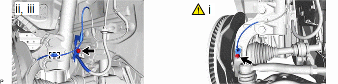
(1) Install the front speed sensor to the steering knuckle with the bolt.
Torque:
8.5 N·m {87 kgf·cm, 75 in·lbf}
NOTICE:
- Keep the tip of the front speed sensor and installation hole free of foreign matter.
- Firmly insert the front speed sensor body into the steering knuckle before tightening the bolt.
- After installing the front speed sensor to the steering knuckle, make sure that there is no clearance between the front speed sensor stay and steering knuckle. Also make sure that no foreign matter is stuck between the parts.
(2) Engage the clamp to the front shock absorber assembly.
(3) Install the front speed sensor clamp and front flexible hose to the front shock absorber assembly with the bolt.
Torque:
29 N·m {296 kgf·cm, 21 ft·lbf}
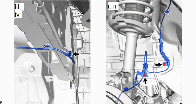
(1) Install the 2 front speed sensor clamps with the 2 bolts.
Torque:
8.5 N·m {87 kgf·cm, 75 in·lbf}
(2) Engage the clamp to the vehicle body.
(3) Engage the clamp to the vehicle body.
(4) Connect the connector.
2. INSTALL FRONT FENDER LINER
3. INSTALL WHEEL OPENING MOULDING
Click here .gif)
4. INSTALL FRONT WHEEL
Click here
5. CHECK FOR SPEED SENSOR SIGNAL
- for HEV Model:
Click here
- for Gasoline Model:
Click here


