Toyota Corolla Cross: Installation
INSTALLATION
CAUTION / NOTICE / HINT
COMPONENTS (INSTALLATION)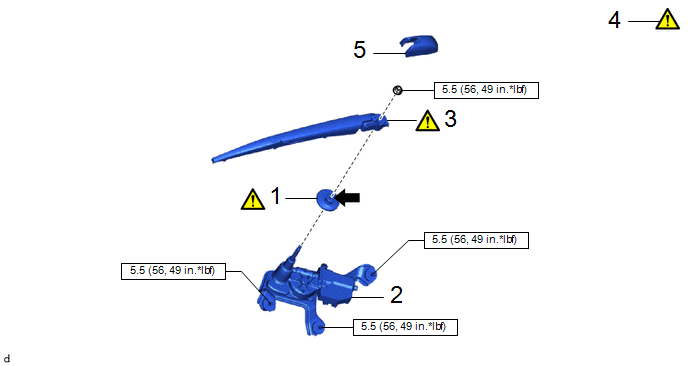
|
Procedure | Part Name Code |
.png) |
.png) |
 |
|---|---|---|---|---|---|
|
1 | REAR WIPER MOTOR GROMMET |
85143R |
|
- | - |
|
2 | REAR WIPER MOTOR ASSEMBLY |
85110R | - |
- | - |
|
3 | INSTALL REAR WIPER ARM AND BLADE ASSEMBLY |
- |
|
- | - |
|
4 | INSPECT REAR WIPER ARM AND BLADE ASSEMBLY |
- |
|
- | - |
|
5 | REAR WIPER ARM HEAD CAP |
85292A | - |
- | - |
.png) |
N*m (kgf*cm, ft.*lbf): Specified torque |
.png) |
MP grease |
|
Procedure | Part Name Code |
|
|
| |
|---|---|---|---|---|---|
|
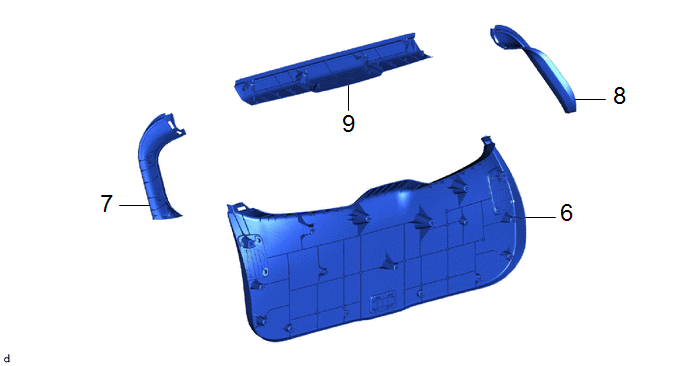
6 | BACK DOOR TRIM PANEL ASSEMBLY |
64780A | - |
- | - |
|
7 | BACK DOOR SIDE GARNISH LH |
67938A | - |
- | - |
|
8 | BACK DOOR SIDE GARNISH RH |
67937B | - |
- | - |
|
9 | UPPER BACK DOOR TRIM PANEL ASSEMBLY |
64790B | - |
- | - |
PROCEDURE
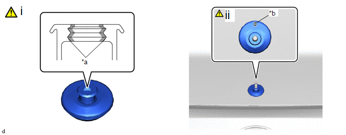
1. INSTALL REAR WIPER MOTOR GROMMET
|
*a | Rear Wiper Motor Grommet Lip |
*b | Alignment Mark |
.png) |
MP grease | - |
- |
(1) Apply MP grease to the entire surface of the rear wiper motor grommet lip.
HINT:
Make sure that the hole does not get clogged with grease and the grooves on the lip are filled with grease.
(2) Install the rear wiper motor grommet.
HINT:
Install the rear wiper motor grommet with its alignment mark facing up.
2. INSTALL REAR WIPER MOTOR ASSEMBLY
Torque:
5.5 N·m {56 kgf·cm, 49 in·lbf}
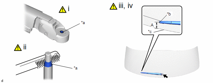
3. INSTALL REAR WIPER ARM AND BLADE ASSEMBLY
|
*a | Serration |
*b | Wiper Set Mark |
|
*c | Back Door Glass Edge Side |
- | - |
(1) When reusing the rear wiper arm and blade assembly:
1. Clean the rear wiper arm serrations to remove any burrs, dirt, etc.
NOTICE:
Do not grind down the wiper arm serrations.
(2) When reusing the rear wiper motor assembly:
1. Clean the wiper pivot serrations with a wire brush.
(3) Set the automatic stop position by the below procedure.
1. Turn the ignition switch ON.
2. Operate the rear wiper motor assembly and stop it at the automatic stop position.
3. Turn the ignition switch off.
(4) Install the rear wiper arm and blade assembly with the nut to the position shown in the illustration.
HINT:
Hold the wiper arm by hand while tightening the nut.
Torque:
5.5 N·m {56 kgf·cm, 49 in·lbf}
Reference Measurement:
|
Area | Measurement |
Area | Measurement |
|---|---|---|---|
|
A | 24.8 to 44.8 mm (0.98 to 1.76 in.) |
- | - |
4. INSPECT REAR WIPER ARM AND BLADE ASSEMBLY
Click here
.gif)
5. INSTALL REAR WIPER ARM HEAD CAP
6. INSTALL BACK DOOR TRIM PANEL ASSEMBLY
7. INSTALL BACK DOOR SIDE GARNISH LH
8. INSTALL BACK DOOR SIDE GARNISH RH
9. INSTALL UPPER BACK DOOR TRIM PANEL ASSEMBLY


