Toyota Corolla Cross: Installation
INSTALLATION
CAUTION / NOTICE / HINT
COMPONENTS (INSTALLATION)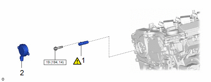
|
Procedure | Part Name Code |
.png) |
.png) |
 |
|---|---|---|---|---|---|
|
1 | CAMSHAFT TIMING VALVE ASSEMBLY (EXHAUST CAMSHAFT TIMING GEAR BOLT ASSEMBLY) |
135A0B |
|
- | - |
|
2 | CAM TIMING OIL CONTROL SOLENOID ASSEMBLY |
15370 | - |
- | - |
.png) |
N*m (kgf*cm, ft.*lbf): Specified torque |
- | - |
CAUTION / NOTICE / HINT
NOTICE:
This procedure includes the installation of small-head bolts. Refer to Small-Head Bolts of Basic Repair Hint to identify the small-head bolts.
Click here .gif)
PROCEDURE
1. INSTALL CAMSHAFT TIMING VALVE ASSEMBLY (EXHAUST CAMSHAFT TIMING GEAR BOLT ASSEMBLY)
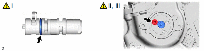
(1) Apply a light coat of engine oil to the O-ring of the camshaft timing oil control valve assembly (exhaust camshaft timing gear bolt assembly).
NOTICE:
If reusing the camshaft timing oil control valve assembly (exhaust camshaft timing gear bolt assembly), be sure to inspect the O-ring.
(2) Temporarily install the camshaft timing oil control valve assembly (exhaust camshaft timing gear bolt assembly) to the camshaft timing exhaust gear assembly.
NOTICE:
If the camshaft timing oil control valve assembly (exhaust camshaft timing gear bolt assembly) has been struck or dropped, replace it.
(3) Using a 5 mm hexagon socket wrench, install the camshaft timing oil control valve assembly (exhaust camshaft timing gear bolt assembly) with the bolt.
Torque:
19 N·m {194 kgf·cm, 14 ft·lbf}
2. INSTALL CAM TIMING OIL CONTROL SOLENOID ASSEMBLY
Click here


