Toyota Corolla Cross: Removal
REMOVAL
CAUTION / NOTICE / HINT
COMPONENTS (REMOVAL)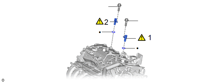
|
Procedure | Part Name Code |
.png) |
.png) |
 |
|---|---|---|---|---|---|
|
1 | CAMSHAFT POSITION SENSOR (for Intake Side) |
11102A |
|
- | - |
|
2 | CAMSHAFT POSITION SENSOR (for Exhaust Side) |
11102A |
|
- | - |
|
● | Non-reusable part |
★ | Precoated part |
CAUTION / NOTICE / HINT
NOTICE:
This procedure includes the removal of small-head bolts. Refer to Small-Head Bolts of Basic Repair Hint to identify the small-head bolts.
Click here .gif)
PROCEDURE
1. REMOVE CAMSHAFT POSITION SENSOR (for Intake Side)
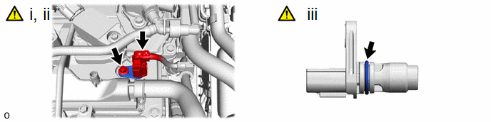
(1) Disconnect the camshaft position sensor connector.
(2) Using an 8 mm socket wrench, remove the bolt and camshaft position sensor from the cylinder head cover sub-assembly.
NOTICE:
If the camshaft position sensor has been struck or dropped, replace it.
(3) Perform this procedure only when reusing the
1. Remove the O-ring from the camshaft position sensor.
NOTICE:
- Make sure to only remove the O-ring with bare hands.
- When removing the O-ring, be careful not to damage the O-ring groove of the camshaft position sensor.
- If the O-ring groove of the camshaft position sensor is damaged, replace the camshaft position sensor with a new one.
2. REMOVE CAMSHAFT POSITION SENSOR (for Exhaust Side)
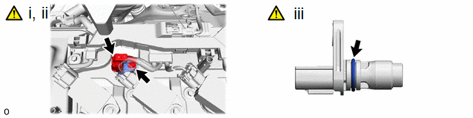
(1) Disconnect the camshaft position sensor connector.
(2) Using an 8 mm socket wrench, remove the bolt and camshaft position sensor from the cylinder head cover sub-assembly.
NOTICE:
If the camshaft position sensor has been struck or dropped, replace it.
(3) Perform this procedure only when reusing the
1. Remove the O-ring from the camshaft position sensor.
NOTICE:
- Make sure to only remove the O-ring with bare hands.
- When removing the O-ring, be careful not to damage the O-ring groove of the camshaft position sensor.
- If the O-ring groove of the camshaft position sensor is damaged, replace the camshaft position sensor with a new one.


