Toyota Corolla Cross: Steering Angle Sensor Wrong Installation (X0455)
DESCRIPTION
|
Code |
Tester Display |
Measurement Item |
Trouble Area |
|---|---|---|---|
|
X0455 |
Steering Angle Sensor Wrong Installation |
History of steering sensor being installed incorrectly |
|
CAUTION / NOTICE / HINT
NOTICE:
After performing the inspection, check and clear the vehicle control history (RoB).
HINT:
When Steering Angle Sensor Wrong Installation (X0455) is stored, output control may operate, but this is not a malfunction.
PROCEDURE
|
1. |
CHECK FOR DTCs (HEALTH CHECK) |
(a) Perform the Health Check using the GTS.
|
Result |
Proceed to |
|---|---|
|
DTCs are not output |
A |
|
DTCs are output |
B |
| B | .gif)
|
GO TO DIAGNOSTIC TROUBLE CODE CHART |
|
.gif)
|
2. |
ALIGN FRONT WHEELS FACING STRAIGHT AHEAD |
|
|
3. |
READ VALUE USING GTS (STEERING ANGLE SIGNAL INFORMATION) |
(a) Check Data List item "Steering Angle Signal Information".
Chassis > Steering Angle Sensor > Data List|
Tester Display |
Measurement Item |
Range |
Normal Condition |
Diagnostic Note |
|---|---|---|---|---|
|
Steering Angle Signal Information |
Steering angle value (Rotation to the left side is positive) |
Min.: -3072.0 deg Max.: 3070.5 deg |
Turning left: 0.0 to 3070.5 deg Turning right: -3072.0 to 0.0 deg |
During steering operation: Changes in proportion with steering wheel rotation |
|
Tester Display |
|---|
|
Steering Angle Signal Information |
(b) Save the steering angle signal information to the GTS memory.
NOTICE:
- If the value is +/- 360 deg (+/-15 deg), the steering sensor was incorrectly installed by 1 rotation.
- If the value is +/- 720 deg (+/-15 deg), the steering sensor was incorrectly installed by 2 rotations.
- In situations other than the above, the steering sensor may have been
incorrectly installed by 3 or more rotations.
In this case, it is possible that the proper installation or removal procedures were not followed, and the steering sensor may have been damaged.
|
Result |
Proceed to |
|---|---|
|
0 deg (+/- 15 deg) |
A |
|
+/- 360 deg (+/-15 deg) or +/- 720 deg (+/-15 deg) |
B |
|
None of the above conditions are met |
C |
| B |
|
GO TO STEP 7 |
| C |
|
GO TO STEP 13 |
|
|
4. |
CLEAR VEHICLE CONTROL HISTORY (RoB) |
(a) Using the GTS, clear the Vehicle Control History (RoB).
Chassis > Brake/EPB > Utility|
Tester Display |
|---|
|
Vehicle Control History (RoB) |
|
|
5. |
PERFORM ZERO POINT CALIBRATION OF STEERING SENSOR |
(a) Disconnect cable from negative (-) auxiliary battery terminal.
HINT:
If the cable is not disconnected from the negative (-) auxiliary battery terminal, it may not be possible to obtain an accurate steering sensor zero point.
(b) Connect cable to negative (-) auxiliary battery terminal.
(c) Drive the vehicle straight ahead at 35 km/h (22 mph) or more for at least 5 seconds.
|
|
6. |
CHECK VEHICLE CONTROL HISTORY (RoB) |
(a) Perform a road test under the same malfunction conditions recreated based on the Freeze Frame Data or customer problem analysis.
(b) Using the GTS, check for Vehicle Control History (RoB).
Chassis > Brake/EPB > Utility|
Tester Display |
|---|
|
Vehicle Control History (RoB) |
|
Result |
Proceed to |
|---|---|
|
X0455 is not output |
A |
|
X0455 is output |
B |
| A |
|
END |
| B |
|
REPLACE STEERING SENSOR |
|
7. |
ADJUST SPIRAL CABLE WITH SENSOR SUB-ASSEMBLY |
(a) Remove the spiral cable with sensor sub-assembly.
Click here .gif)
NOTICE:
- Be sure to disconnect the cable from the negative (-) auxiliary battery
terminal before removing the spiral cable with sensor sub-assembly.
HINT:
If the cable is not disconnected from the negative (-) auxiliary battery terminal, it may not be possible to obtain an accurate steering sensor zero point.
- Do not disconnect the steering sensor from the spiral cable.
|
(b) Based on the internal steering angle value that was saved to the GTS memory earlier, rotate the spiral cable with sensor sub-assembly. |
|
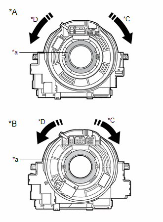
NOTICE:
- Rotate the steering sensor without disconnecting it from the spiral cable.
- Make sure to follow the adjustment method shown in the table.
- Failure to observe the following precautions may result in damage to
the spiral cable with sensor sub-assembly.
- When rotating the spiral cable with sensor sub-assembly, make sure to push on the interlock to release the interlock.
- Do not turn the spiral cable with sensor sub-assembly using the airbag wire harness.
- Do not forcibly rotate the part.
- Make sure to perform the correct number of rotations in the correct direction.
|
Steering Angle Signal Information |
Correction Method |
|---|---|
|
360 deg (+/-15 deg) |
Rotate clockwise (to the right), 1 rotation. |
|
- 360 deg (+/-15 deg) |
Rotate counterclockwise (to the left), 1 rotation. |
|
720 deg (+/-15 deg) |
Rotate clockwise (to the right), 2 rotations. |
|
- 720 deg (+/-15 deg) |
Rotate counterclockwise (to the left), 2 rotations. |
(c) Install the spiral cable with sensor sub-assembly.
Click here
|
|
8. |
ALIGN FRONT WHEELS FACING STRAIGHT AHEAD |
|
|
9. |
READ VALUE USING GTS (STEERING ANGLE SIGNAL INFORMATION) |
(a) Check Data List item "Steering Angle Signal Information".
Chassis > Steering Angle Sensor > Data List|
Tester Display |
Measurement Item |
Range |
Normal Condition |
Diagnostic Note |
|---|---|---|---|---|
|
Steering Angle Signal Information |
Steering angle value (Rotation to the left side is positive) |
Min.: -3072.0 deg Max.: 3070.5 deg |
Turning left: 0.0 to 3070.5 deg Turning right: -3072.0 to 0.0 deg |
During steering operation: Changes in proportion with steering wheel rotation. |
|
Tester Display |
|---|
|
Steering Angle Signal Information |
|
Result |
Proceed to |
|---|---|
|
0 deg (+/- 15 deg) |
A |
|
None of the above conditions are met |
B |
| B |
|
REPLACE STEERING SENSOR |
|
|
10. |
CLEAR VEHICLE CONTROL HISTORY (RoB) |
(a) Using the GTS, clear the Vehicle Control History (RoB).
Chassis > Brake/EPB > Utility|
Tester Display |
|---|
|
Vehicle Control History (RoB) |
|
|
11. |
PERFORM ZERO POINT CALIBRATION OF STEERING SENSOR |
(a) Drive the vehicle straight ahead at 35 km/h (22 mph) or more for at least 5 seconds.
|
|
12. |
CHECK VEHICLE CONTROL HISTORY (RoB) |
(a) Perform a road test under the same malfunction conditions recreated based on the Freeze Frame Data or customer problem analysis.
(b) Using the GTS, check for Vehicle Control History (RoB).
Chassis > Brake/EPB > Utility|
Tester Display |
|---|
|
Vehicle Control History (RoB) |
|
Result |
Proceed to |
|---|---|
|
X0455 is not output |
A |
|
X0455 is output |
B |
| A |
|
END |
| B |
|
REPLACE STEERING SENSOR |
|
13. |
CHECK STEERING WHEEL ASSEMBLY CENTER POSITION |
(a) Perform steering wheel assembly center position adjustment.
Click here
|
|
14. |
ADJUST WHEEL ALIGNMENT |
for front wheel alignment: Click here
for rear wheel alignment (for 2WD): Click here
for rear wheel alignment (for AWD): Click here
|
|
15. |
CLEAR VEHICLE CONTROL HISTORY (RoB) |
(a) Using the GTS, clear the Vehicle Control History (RoB).
Chassis > Brake/EPB > Utility|
Tester Display |
|---|
|
Vehicle Control History (RoB) |
|
|
16. |
PERFORM STEERING SENSOR ZERO POINT CALIBRATION |
(a) Disconnect cable from negative (-) auxiliary battery terminal.
HINT:
If the cable is not disconnected from the negative (-) auxiliary battery terminal, it may not be possible to obtain an accurate steering sensor zero point.
(b) Connect cable to negative (-) auxiliary battery terminal.
(c) Drive the vehicle straight ahead at 35 km/h (22 mph) or more for at least 5 seconds.
|
|
17. |
CHECK VEHICLE CONTROL HISTORY (RoB) |
(a) Perform a road test under the same malfunction conditions recreated based on the Freeze Frame Data or customer problem analysis.
(b) Using the GTS, check for Vehicle Control History (RoB).
Chassis > Brake/EPB > Utility|
Tester Display |
|---|
|
Vehicle Control History (RoB) |
|
Result |
Proceed to |
|---|---|
|
X0455 is not output |
A |
|
X0455 is output |
B |
| A |
|
END |
| B |
|
REPLACE STEERING SENSOR |


