Toyota Corolla Cross: Parts Location
PARTS LOCATION
ILLUSTRATION
|
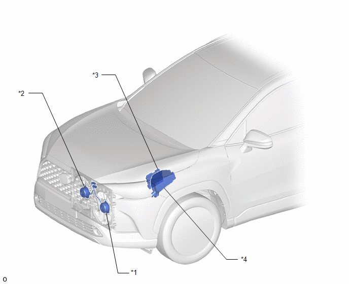
*1 | COOLING FAN MOTOR LH |
*2 | COOLING FAN MOTOR RH |
|
*3 | ECM |
*4 | NO. 1 ENGINE ROOM RELAY BLOCK AND NO. 1 JUNCTION BLOCK ASSEMBLY
- NO. 1 INTEGRATION RELAY (EFI-MAIN RELAY) - FAN NO. 2 RELAY
- FAN NO. 3 RELAY |
READ NEXT:
PROBLEM SYMPTOMS TABLE
HINT:
Use the table below to help determine the cause of problem symptoms. If multiple suspected areas are listed, the potential causes of the symptoms are listed in order
ON-VEHICLE INSPECTION CAUTION / NOTICE / HINT
CAUTION:
When working near the engine room while the engine has started or the power source mode is ignition switch to ON, do not touch the rotating
SEE MORE:
DESCRIPTION As this DTC is not normally output, it may be due to noise in the LIN communication system, etc.
DTC No. Detection Item
DTC Detection Condition Trouble Area
Note B278187
Steering Lock System Missing Message
One of the following conditions is met (1-tri
PARTS LOCATION ILLUSTRATION
*1 FAN WITH MOTOR ASSEMBLY
*2 ECM
*3 NO. 1 ENGINE ROOM RELAY BLOCK AND NO. 1 JUNCTION BLOCK ASSEMBLY
- EFI-MAIN NO. 1 FUSE - FAN NO. 2 FUSE - EFI NO. 3 FUSE
- EFI-MAIN NO. 1 Relay
*4 FUSIBLE LINK BLOCK ASSEMBLY
- ALT FUSE


