Toyota Corolla Cross: System Diagram
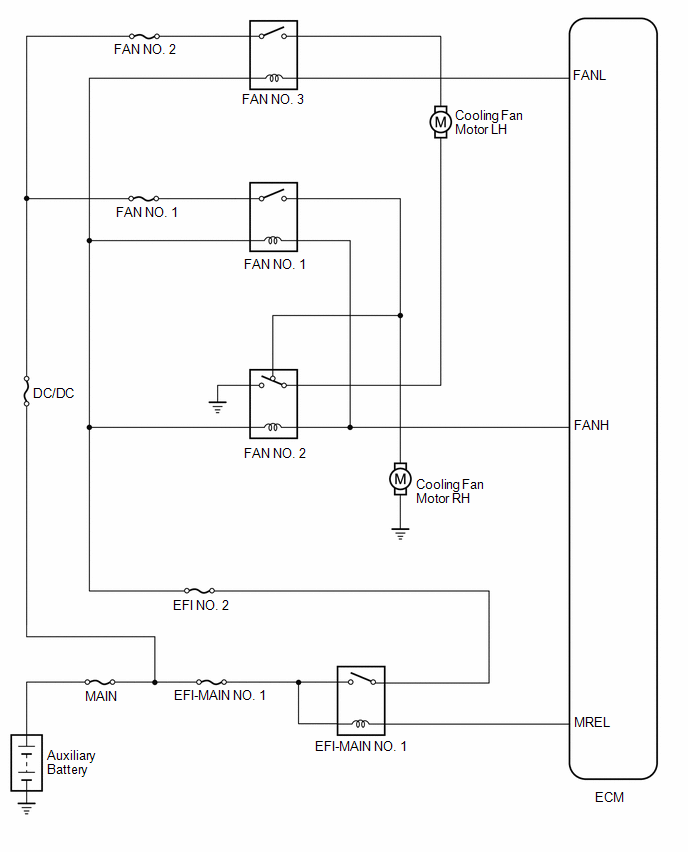
SYSTEM DIAGRAM
READ NEXT:
PROBLEM SYMPTOMS TABLE
HINT:
Use the table below to help determine the cause of problem symptoms. If multiple suspected areas are listed, the potential causes of the symptoms are listed in order
ON-VEHICLE INSPECTION CAUTION / NOTICE / HINT
CAUTION:
When working near the engine room while the engine has started or the power source mode is ignition switch to ON, do not touch the rotating
DESCRIPTION The ECM turns on or off the fan relays using signals calculated from the engine coolant temperature, air conditioning switch (on/off), air conditioning refrigerant pressure, engine speed a
SEE MORE:
INSTALLATION CAUTION / NOTICE / HINT COMPONENTS (INSTALLATION)
Procedure Part Name Code
1 FUEL SUCTION TUBE WITH PUMP AND GAUGE ASSEMBLY
77020A
- -
2 FUEL PUMP GAUGE RETAINER
77144
- -
3 NO. 1 FU
Components
COMPONENTS
ILLUSTRATION
*1
REAR ENGINE UNDER COVER LH
*2
RADIATOR CAP SUB-ASSEMBLY
*3
RADIATOR DRAIN COCK PLUG
-
-
Replacement
REPLACEMENT
PROCEDURE
1. REMOVE REAR ENGINE UN
 Problem Symptoms Table
 Installation
