Toyota Corolla Cross: Installation
INSTALLATION
CAUTION / NOTICE / HINT
COMPONENTS (INSTALLATION)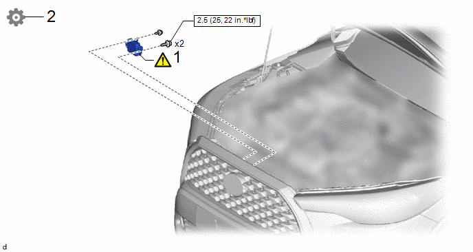
|
Procedure |
Part Name Code |
.png) |
.png) |
.png) |
|
|---|---|---|---|---|---|
|
1 |
INSTALL MILLIMETER WAVE RADAR SENSOR ASSEMBLY |
88211B |
|
- |
- |
|
2 |
ADJUST MILLIMETER WAVE RADAR SENSOR ASSEMBLY |
88211B |
- |
- |
|
 |
N*m (kgf*cm, ft.*lbf): Specified torque |
- |
- |
PROCEDURE
1. INSTALL MILLIMETER WAVE RADAR SENSOR ASSEMBLY
|
|
NOTICE: If the millimeter wave radar sensor assembly has been struck or dropped, replace the millimeter wave radar sensor assembly with a new one. |

.png) |
Bolt |
.png) |
Screw |
(1) Engage the guides to temporarily install the millimeter wave radar sensor assembly.
(2) Install the millimeter wave radar sensor assembly with the 2 bolts and screw.
Torque:
Bolt :
2.5 N·m {25 kgf·cm, 22 in·lbf}
HINT:
Tighten the bolts and screw in the order shown in the illustration.
(3) Connect the connector.
2. ADJUST MILLIMETER WAVE RADAR SENSOR ASSEMBLY
(a) When the millimeter wave radar sensor assembly is replaced with a new one, adjustment of the radar sensor beam axis must be performed.
HINT:
Millimeter wave radar sensor assembly learning can be performed by using either Triangle Target, Flat Surface Target or Driving Adjustment.
- Triangle Target:
Click here
.gif)
- Flat Surface Target:
Click here
- Driving Adjustment:
Click here


