Toyota Corolla Cross: Control Module Processor (Brake Override System Input Signal) Component Failure (P161009)
DESCRIPTION
The ECM monitors for malfunction displays during brake override system input information (stop light switch assembly, speed sensor) malfunctions.
|
DTC No. | Detection Item |
DTC Detection Condition | Trouble Area |
MIL | Note |
|---|---|---|---|---|---|
|
P161009 | Control Module Processor (Brake Override System Input Signal) Component Failure |
Any of the following conditions are met (1 trip detection logic).
| ECM |
Does not come on |
|
MONITOR DESCRIPTION
The ECM compares input signal information for brake override system control calculations for control and monitoring. If the ECM determines a malfunction mode in which brake override system operation conditions are not met, a DTC is stored to indicate the brake override system malfunction.
MONITOR STRATEGY
|
Required Sensors/Components | Stop light switch assembly Speed sensor |
| Frequency of Operation |
Continuous |
CONFIRMATION DRIVING PATTERN

- Connect the GTS to the DLC3.
- Turn the ignition switch to ON.
- Turn the GTS on.
- Clear the DTCs (even if no DTCs are stored, perform the clear DTC procedure).
- Turn the GTS off.
- Turn the ignition switch off and wait for at least 30 seconds.
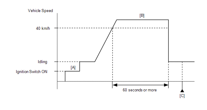
- Turn the ignition switch to ON [A].
- Turn the GTS on.
- Start the engine.
- Drive the vehicle at 40 km/h (25 mph) or more for 60 seconds or more [B].
CAUTION:
When performing the confirmation driving pattern, obey all speed limits and traffic laws.
- Enter the following menus: Powertrain / Engine / Trouble Codes [C].
- Read the pending DTCs.
HINT:
- If a pending DTC is output, the system is malfunctioning.
- If a pending DTC is not output, perform the following procedure.
- Enter the following menus: Powertrain / Engine / Utility / All Readiness.
- Input the DTC: P161009.
- Check the DTC judgment result.
GTS Display
Description
NORMAL
- DTC judgment completed
- System normal
ABNORMAL
- DTC judgment completed
- System abnormal
INCOMPLETE
- DTC judgment not completed
- Perform driving pattern after confirming DTC enabling conditions
HINT:
- If the judgment result is NORMAL, the system is normal.
- If the judgment result is ABNORMAL, the system is malfunctioning.
- If the judgment result is INCOMPLETE, perform steps [A] through [C].
CAUTION / NOTICE / HINT
HINT:
Read Freeze Frame Data using the GTS. The ECM records vehicle and driving condition information as Freeze Frame Data the moment a DTC is stored. When troubleshooting, Freeze Frame Data can help determine if the vehicle was moving or stationary, if the engine was warmed up or not, if the air fuel ratio was lean or rich, and other data from the time the malfunction occurred.
PROCEDURE
| 1. |
CLEAR DTC |
(a) Clear the DTCs.
Powertrain > Engine > Clear DTCs(b) Turn the ignition switch off and wait for at least 30 seconds.
|
| 2. |
READ OUTPUT DTC (DTC P161009) |
(a) Drive the vehicle in accordance with the driving pattern described in Confirmation Driving Pattern.
(b) Read the DTCs.
Powertrain > Engine > Trouble Codes|
Result | Proceed to |
|---|---|
|
DTCs are not output | A |
|
DTC P161009 is output |
B |
| A |
.gif) | CHECK FOR INTERMITTENT PROBLEMS |
| B |
.gif) | REPLACE ECM
|

.gif)
.gif)

