
Toyota Corolla Cross: Inspection
INSPECTION
PROCEDURE
1. INSPECT REAR HEIGHT CONTROL SENSOR SUB-ASSEMBLY LH (for 2WD)
(a) Preparation for check.
(1) Confirm the standard, high and low positions of the link that will be used in the following inspection.
- The standard position is 53° from the maximum link angle (high) and 113° from the maximum link angle (low).
- The high position (+36.7°) is 16.3° from the maximum link angle (high).
- The low position (-33.5°) is 79.5° from the maximum link angle (low).
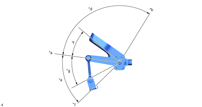
|
*a | Standard Position |
*b | Maximum Link Angle (Low) |
|
*c | Maximum Link Angle (High) |
*d | 113° |
|
*e | 53° |
*f | -33.5° |
|
*g | +36.7° | - |
- |
(2) Connect 3 dry cell batteries (1.5 V) in series.
NOTICE:
Do not use rechargeable batteries as they may not output a voltage of 1.5 V.
(3) Connect a positive (+) lead from the batteries to Q1-3 (SHB) and a negative (-) lead to Q1-1 (SHG).
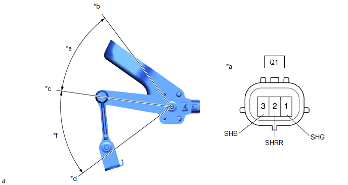
|
*a | Component without harness connected (Rear Height Control Sensor Sub-assembly LH) |
*b | Low |
|
*c | Standard Position |
*d | High |
|
*e | -45° |
*f | +45° |
(4) Measure the voltage between Q1-2 (SHRR) and Q1-1 (SHG) while slowly moving the link up and down.
Standard Voltage:
|
Tester Connection | Condition |
Specified Condition |
|---|---|---|
|
Q1-1 (SHG) - Q1-2 (SHRR) |
+45° (High) | 4.5 V |
|
Q1-1 (SHG) - Q1-2 (SHRR) |
0° (Standard position) |
2.5 V |
| Q1-1 (SHG) - Q1-2 (SHRR) |
-45° (Low) | 0.5 V |
If the result is not as specified, replace the rear height control sensor sub-assembly LH.
2. INSPECT REAR HEIGHT CONTROL SENSOR SUB-ASSEMBLY LH (for AWD)
(a) Preparation for check
(1) Confirm the standard, high and low positions of the link that will be used in the following inspection.
- The standard position is 58° from the maximum link angle (high) and 51° from the maximum link angle (low).
- The high position (+33.85°) is 24.15° from the maximum link angle (high).
- The low position (-33.85°) is 17.15° from the maximum link angle (low).
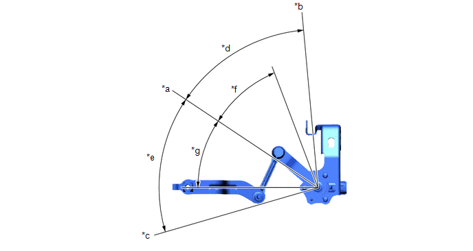
|
*a | Standard Position |
*b | Maximum Link Angle (Low) |
|
*c | Maximum Link Angle (High) |
*d | 51° |
|
*e | 58° |
*f | -33.85° |
|
*g | +33.85° | - |
- |
(2) Connect 3 dry cell batteries (1.5 V) in series.
NOTICE:
Do not use rechargeable batteries as they may not output a voltage of 1.5 V.
(3) Connect a positive (+) lead from the batteries to Q1-3 (SHB) and a negative (-) lead to Q1-1 (SHG).
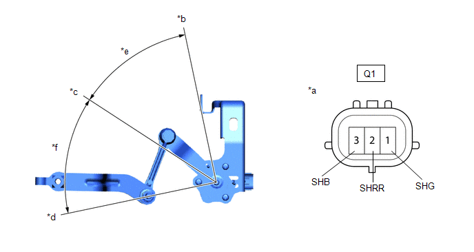
|
*a | Component without harness connected (Rear Height Control Sensor Sub-assembly LH) |
*b | Low |
|
*c | Standard Position |
*d | High |
|
*e | -45° |
*f | +45° |
(4) Measure the voltage between terminals 2 (SHRR) and 1 (SHG) while slowly moving the link up and down.
Standard Voltage:
|
Tester Connection | Condition |
Specified Condition |
|---|---|---|
|
Q1-1 (SHG) - Q1-2 (SHRR) |
+45° (High) | 4.5 V |
|
Q1-1 (SHG) - Q1-2 (SHRR) |
0° (Standard position) |
2.5 V |
| Q1-1 (SHG) - Q1-2 (SHRR) |
-45° (Low) | 0.5 V |
If the result is not as specified, replace the rear height control sensor sub-assembly LH.


