Toyota Corolla Cross: Terminals Of Ecu
TERMINALS OF ECU
CHECK POWER DISTRIBUTION BOX ASSEMBLY AND MAIN BODY ECU (MULTIPLEX NETWORK BODY ECU)
(a) Remove the main body ECU (multiplex network body ECU).
Click here
.gif)
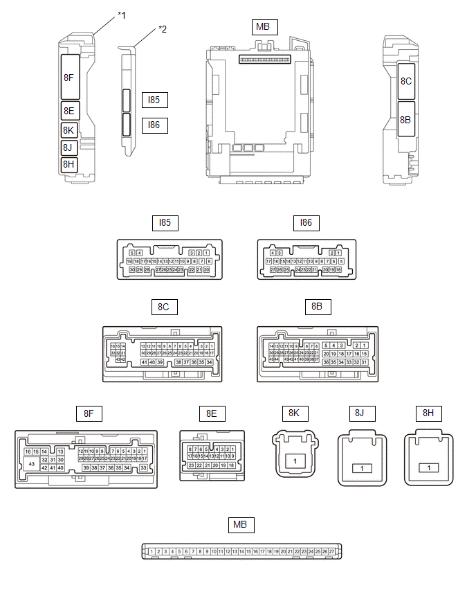
|
*1 | Power Distribution Box Assembly |
*2 | Main Body ECU (Multiplex Network Body ECU) |
(b) Reconnect the power distribution box assembly connectors.
Click here
(c) Measure the voltage and resistance according to the value(s) in the table below.
|
Terminal No. (Symbol) | Terminal Description |
Condition | Specified Condition |
|---|---|---|---|
|
MB-13 (GND1) - Body ground |
Ground | Always |
Below 1 Ω |
|
MB-26 (BECU) - Body ground |
Auxiliary battery power supply |
Ignition switch off | 11 to 14 V |
|
MB-27 (IGR) - Body ground |
IG power supply | Ignition switch off |
Below 1 V |
|
Ignition switch ON | 11 to 14 V |
(d) Install the main body ECU (multiplex network body ECU).
Click here
(e) Measure the voltage and check for pulses according to the value(s) in the table below.
|
Terminal No. (Symbol) | Terminal Description |
Condition | Specified Condition |
|---|---|---|---|
|
8B-2 - Body ground |
Mirror heater drive signal |
Ignition switch ON, rear window defogger switch off |
Below 1 V |
|
Ignition switch ON, rear window defogger switch on |
11 to 14 V |
CHECK AIR CONDITIONING AMPLIFIER ASSEMBLY
Click here
AIR CONDITIONING CONTROL ASSEMBLY
Click here


