
Toyota Corolla Cross: Mirror Heater does not Operate with Rear Defogger Switch
DESCRIPTION
When the mirror heater switch (rear window defogger switch) is operated, the RR DEF relay drive request signal is sent to the air conditioning amplifier assembly and then to main body ECU (multiplex network body ECU) via CAN communication. When the main body ECU (multiplex network body ECU) receives the RR DEF relay drive request signal, it sends a mirror heater operation signal to the power distribution box assembly.
Based on this signal, the power distribution box assembly operate the mirror heaters.
WIRING DIAGRAM
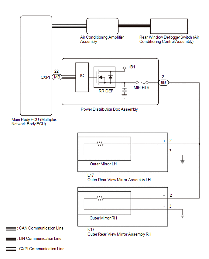
CAUTION / NOTICE / HINT
NOTICE:
- Inspect the fuses for circuits related to this system before performing the following procedure.
- If the auxiliary battery voltage becomes low, auxiliary battery load control will operate in order to ensure sufficient power is supplied to the power steering system. In this case, the window defogger system may not operate.
- When replacing the power distribution box assembly, the system may not operate normally if the same part number is not used.
- The power mirror control system uses the CAN communication system, LIN communication system and CXPI communication system. Inspect the communication function by following How to Proceed with Troubleshooting. Troubleshoot the power mirror control system after confirming that the communication system is functioning properly.
Click here
.gif)
PROCEDURE
|
1. | CHECK VEHICLE CONDITION |
(a) Check vehicle condition.
|
Result | Proceed to |
|---|---|
|
Both mirror heater does not operate |
A |
| LH side mirror heater does not operate |
B |
| RH side mirror heater does not operate |
C |
| B |
.gif) | GO TO STEP 6 |
| C |
| GO TO STEP 8 |
|
.gif)
| 2. |
CHECK WINDOW DEFOGGER SYSTEM |
(a) Check the window defogger system operation.
Click here
OK:
The window defogger system operates normally.
| NG | | GO TO WINDOW DEFOGGER SYSTEM
|
|
| 3. |
CHECK HARNESS AND CONNECTOR (OUTER REAR VIEW MIRROR ASSEMBLY - POWER DISTRIBUTION BOX ASSEMBLY AND BODY GROUND) |
(a) Disconnect the L17 outer rear view mirror assembly LH connector.
(b) Disconnect the K17 outer rear view mirror assembly RH connector.
(c) Disconnect the 8B power distribution box assembly connector.
(d) Measure the resistance according to the value(s) in the table below.
Standard Resistance:
LH Side|
Tester Connection | Condition |
Specified Condition |
|---|---|---|
|
L17-2 (+) - 8B-2 | Always |
Below 1 Ω |
|
L17-3 (-) - Body Ground |
Always | Below 1 Ω |
|
L17-2 (+) or 8B-2 - Body ground |
Always | 10 kΩ or higher |
|
Tester Connection | Condition |
Specified Condition |
|---|---|---|
|
K17-2 (+) - 8B-2 | Always |
Below 1 Ω |
|
K17-3 (-) - Body Ground |
Always | Below 1 Ω |
|
K17-2 (+) or 8B-2 - Body ground |
Always | 10 kΩ or higher |
| NG | | REPAIR OR REPLACE HARNESS OR CONNECTOR |
|
| 4. |
INSPECT OUTER REAR VIEW MIRROR ASSEMBLY LH |
Click here
| NG | | GO TO STEP 7 |
|
| 5. |
INSPECT OUTER REAR VIEW MIRROR ASSEMBLY RH |
Click here
| OK | | REPLACE POWER DISTRIBUTION BOX ASSEMBLY
|
| NG | | GO TO STEP 9 |
| 6. |
CHECK HARNESS AND CONNECTOR (OUTER REAR VIEW MIRROR ASSEMBLY LH - POWER DISTRIBUTION BOX ASSEMBLY) |
(a) Disconnect the L17 outer rear view mirror assembly LH connector.
(b) Disconnect the 8B power distribution box assembly connector.
(c) Measure the resistance according to the value(s) in the table below.
Standard Resistance:
|
Tester Connection | Condition |
Specified Condition |
|---|---|---|
|
L17-2 (+) - 8B-2 | Always |
Below 1 Ω |
|
L17-3 (-) - Body Ground |
Always | Below 1 Ω |
| NG | | REPAIR OR REPLACE HARNESS OR CONNECTOR |
|
| 7. |
INSPECT OUTER MIRROR LH |
Click here
| OK | |
REPLACE OUTER REAR VIEW MIRROR ASSEMBLY LH |
| NG | | REPLACE OUTER MIRROR LH |
| 8. |
CHECK HARNESS AND CONNECTOR (OUTER REAR VIEW MIRROR ASSEMBLY RH - POWER DISTRIBUTION BOX ASSEMBLY) |
(a) Disconnect the K17 outer rear view mirror assembly RH connector.
(b) Disconnect the 8B power distribution box assembly connector.
(c) Measure the resistance according to the value(s) in the table below.
Standard Resistance:
|
Tester Connection | Condition |
Specified Condition |
|---|---|---|
|
K17-2 (+) - 8B-2 | Always |
Below 1 Ω |
|
K17-3 (-) - Body Ground |
Always | Below 1 Ω |
| NG | | REPAIR OR REPLACE HARNESS OR CONNECTOR |
|
| 9. |
INSPECT OUTER MIRROR RH |
Click here
| OK | |
REPLACE OUTER REAR VIEW MIRROR ASSEMBLY RH |
| NG | | REPLACE OUTER MIRROR RH |


