Toyota Corolla Cross: System Diagram
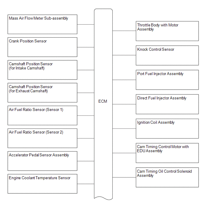
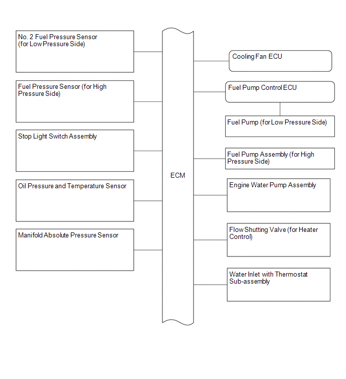
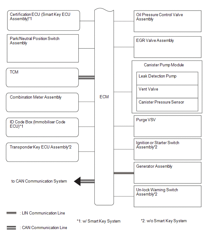
SYSTEM DIAGRAM
READ NEXT:
CAUTION / NOTICE / HINT HINT: *: Use the GTS. PROCEDURE
1.
VEHICLE BROUGHT TO WORKSHOP
NEXT
2.
CUSTOMER PROBLEM ANALYSIS
NEXT
CHECK FOR INTERMITTENT PROBLEMS HINT: Inspect the vehicle ECM using check mode. Intermittent problems are easier to detect with the GTS when the ECM is in check mode. In check mode, the ECM uses 1 tri
CAUTION / NOTICE / HINT When a malfunction is not confirmed by the DTC check, troubleshooting should be carried out for all circuits considered to be possible causes of the problem. In many cases, by
SEE MORE:
DESCRIPTION This DTC is stored when a door control transmitter assembly with a different vehicle serial number is inserted into the ignition key cylinder.
DTC No. Detection Item
DTC Detection Condition Trouble Area
Note B2795
Unmatched Key Code A door control transmit
DESCRIPTION
This DTC is stored when a malfunction occurs in the stereo component
amplifier assembly.
DTC No.
Detection Item
DTC Detection Condition
Trouble Area
DTC Output from
Priority
B15A396
Stereo C
 How To Proceed With Troubleshooting
 Unmatched Key Code (B2795)
