Toyota Corolla Cross: Removal
REMOVAL
CAUTION / NOTICE / HINT
COMPONENTS (REMOVAL)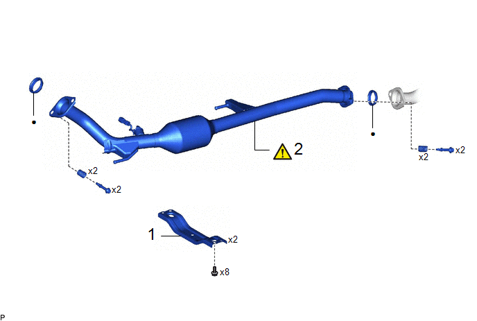
|
Procedure |
Part Name Code |
.png) |
.png) |
.png) |
|
|---|---|---|---|---|---|
|
1 |
FRONT FLOOR CENTER BRACE |
57533B |
- |
- |
- |
|
2 |
FRONT EXHAUST PIPE ASSEMBLY |
17410 |
|
- |
- |
|
● |
Non-reusable part |
- |
- |
|
Procedure |
Part Name Code |
|
|
|
|
|---|---|---|---|---|---|
|
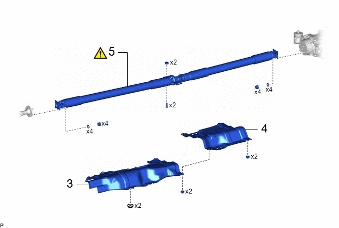
3 |
FRONT LOWER NO. 1 FLOOR HEAT INSULATOR |
58152A |
- |
- |
- |
|
4 |
FRONT NO. 2 FLOOR HEAT INSULATOR |
58153 |
- |
- |
- |
|
5 |
PROPELLER SHAFT WITH CENTER BEARING ASSEMBLY |
37100 |
|
- |
- |
CAUTION / NOTICE / HINT
CAUTION:
- When the engine is hot, do not touch high-temperature areas such as the
engine or exhaust pipe.
.png)
- Touching high-temperature areas such as the engine and exhaust pipe could result in burns.
PROCEDURE
1. REMOVE FRONT FLOOR CENTER BRACE
Click here .gif)
2. REMOVE FRONT EXHAUST PIPE ASSEMBLY
|
|
Click here |
3. REMOVE FRONT LOWER NO. 1 FLOOR HEAT INSULATOR

4. REMOVE FRONT NO. 2 FLOOR HEAT INSULATOR

5. REMOVE PROPELLER SHAFT WITH CENTER BEARING ASSEMBLY
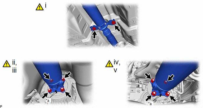
|
*a |
Matchmark |
- |
- |
(1) Remove the 2 bolts and 2 center No. 2 support bearing washers, and separate the center support bearing.
NOTICE:
- When removing the propeller shaft with center bearing assembly, do not apply excessive force to the universal joint.
- During and after the removal of the propeller shaft with center bearing assembly, keep the universal joint angle straight (within 20 degrees).
(2) Place matchmarks on the rear differential carrier assembly and propeller shaft with center bearing assembly.
(3) Remove the 4 nuts and 4 washers, and separate the propeller shaft with center bearing assembly from the rear differential carrier assembly.
(4) Place matchmarks on the transfer assembly and propeller shaft with center bearing assembly.
(5) Remove the 4 nuts and 4 washers, and separate the propeller shaft with center bearing assembly from the transfer assembly.


