Toyota Corolla Cross Owners & Service Manuals

Toyota Corolla Cross: Inspection

INSPECTION

PROCEDURE

1. INSPECT PROPELLER SHAFT WITH CENTER BEARING ASSEMBLY

(a) Using a dial indicator, measure the runout of the intermediate shaft assembly.

Maximum Runout:

0.6 mm (0.0236 in.)

NOTICE:

The dial indicator must be set at a right angle to the center of the intermediate shaft assembly.

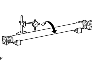
(b) If the runout is more than the maximum, replace the propeller shaft with center bearing assembly.

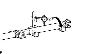
(c) Using a dial indicator, measure the runout of the propeller shaft assembly.

Maximum Runout:

0.4 mm (0.0157 in.)

If the runout is more than the maximum, replace the propeller shaft with center bearing assembly.

NOTICE:

The dial indicator must be set at a right angle to the center of the propeller shaft assembly.

(d) Check that there is no excessive play and the joint part moves smoothly when moving the joint part up and down, left and right, and in the direction of the axis.

    READ NEXT:

     Reassembly

    REASSEMBLY CAUTION / NOTICE / HINT COMPONENTS (REASSEMBLY) Procedure Part Name Code 1 UNIVERSAL BOOT KIT -

     Installation

    INSTALLATION CAUTION / NOTICE / HINT COMPONENTS (INSTALLATION) Procedure Part Name Code 1 TEMPORARILY INSTALL PROPELLER

     Propeller Shaft System

    Problem Symptoms Table PROBLEM SYMPTOMS TABLE HINT: Use the table below to help determine the cause of problem symptoms. If multiple suspected areas are listed, the potential causes of the symp

    SEE MORE:

     Installation

    INSTALLATION CAUTION / NOTICE / HINT COMPONENTS (INSTALLATION) Procedure Part Name Code 1 NO. 2 EXHAUST MANIFOLD HEAT INSULATOR 17168 - - - 2 EXHAUST MANIFOLD (TWC: Front Catalyst) 17141 - - 3 MANIFOLD

     Diagnostic Trouble Code Chart

    DIAGNOSTIC TROUBLE CODE CHART Front Camera System DTC No. Detection Item DTC Output from Link B150E94 Instrument Panel Cluster (IPC) Control Module Unexpected Operation Front Recognition Camera

    © 2020-2025 Copyright www.tcorollacross.com PT NL