Toyota Corolla Cross: Disassembly
DISASSEMBLY
CAUTION / NOTICE / HINT
COMPONENTS (DISASSEMBLY)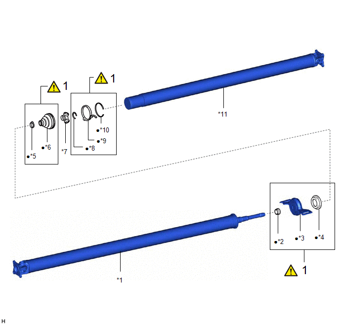
|
Procedure |
Part Name Code |
.png) |
.png) |
.png) |
|
|---|---|---|---|---|---|
|
1 |
UNIVERSAL BOOT KIT |
- |
|
- |
- |
.gif)
|
*1 |
FRONT PROPELLER SHAFT ASSEMBLY |
*2 |
NO. 1 DUST DEFLECTOR |
|
*3 |
CENTER SUPPORT BEARING |
*4 |
FLANGE |
|
*5 |
SMALL DIAMETER PROPELLER SHAFT BOOT CLAMP |
*6 |
PROPELLER SHAFT BOOT |
|
*7 |
TRIPOD JOINT |
*8 |
PROPELLER SHAFT SNAP RING |
|
*9 |
LARGE DIAMETER PROPELLER SHAFT BOOT CLAMP |
*10 |
BEARING CASE SNAP RING |
|
*11 |
REAR PROPELLER SHAFT ASSEMBLY |
- |
- |
|
● |
Non-reusable part |
- |
- |
CAUTION / NOTICE / HINT
NOTICE:
- As imbalance affects vibration and noise performance, make sure to ensure
correct angular alignment of the following components during installation.
- FRONT PROPELLER SHAFT ASSEMBLY
- REAR PROPELLER SHAFT ASSEMBLY
- LARGE DIAMETER PROPELLER SHAFT BOOT CLAMP
- SMALL DIAMETER PROPELLER SHAFT BOOT CLAMP
- TRIPOD JOINT
PROCEDURE
1. REMOVE UNIVERSAL BOOT KIT
HINT:
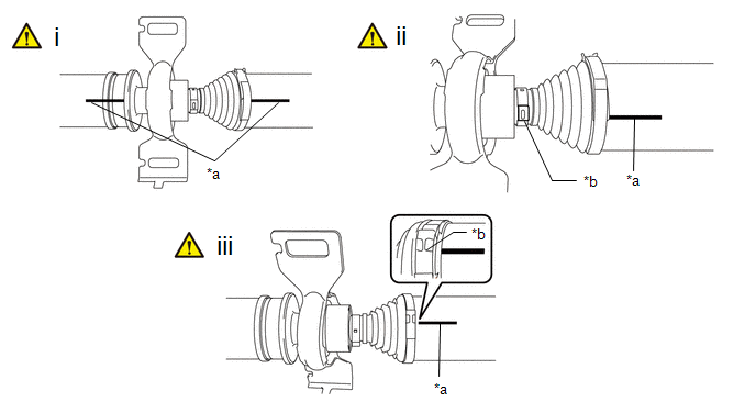
As the rear propeller shaft assembly requires alignment of multiple matchmarks, it is necessary to make separately distinguishable matchmarks.
|
*a |
Matchmark |
*b |
Crimp position |
(1) Put matchmarks on the front propeller shaft assembly and rear propeller shaft assembly.
NOTICE:
Do not use a punch for the marks.
(2) Put a matchmark on the rear propeller shaft assembly in alignment with the crimp position of the small diameter propeller shaft boot clamp.
(3) Put a matchmark on the rear propeller shaft assembly in alignment with the crimp position of the large diameter propeller shaft boot clamp.
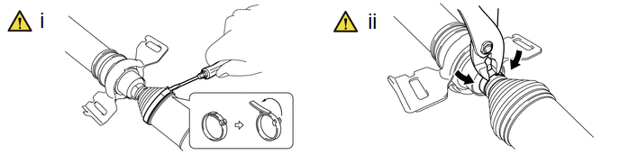
(1) Using a screwdriver, release the crimp of the large diameter propeller shaft boot clamp and separate the large diameter propeller shaft boot clamp from the propeller shaft boot.
(2) Using pliers, grip the crimp area of the clamp and pry the area of the small diameter propeller shaft boot clamp shown in the illustration to separate the small diameter propeller shaft boot clamp from the propeller shaft boot.
|
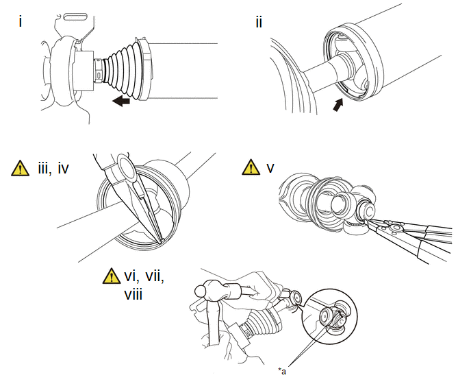
*a |
Matchmark |
- |
- |
(1) Separate the propeller shaft boot from the rear propeller shaft assembly.
(2) Remove the old grease from the joint part.
(3) Using needle-nose pliers, remove the bearing case snap ring.
(4) Remove the rear propeller shaft assembly from the front propeller shaft assembly.
(5) Using a snap ring expander, remove the propeller shaft snap ring.
(6) Put matchmarks on the rear propeller shaft assembly and tripod joint.
NOTICE:
Do not use a punch for the marks.
(7) Using a brass bar and a hammer, tap out the tripod joint from the front propeller shaft assembly.
NOTICE:
- Do not tap the rollers.
- Do not drop the tripod joint.
(8) Remove the propeller shaft boot and 2 propeller shaft boot clamps.
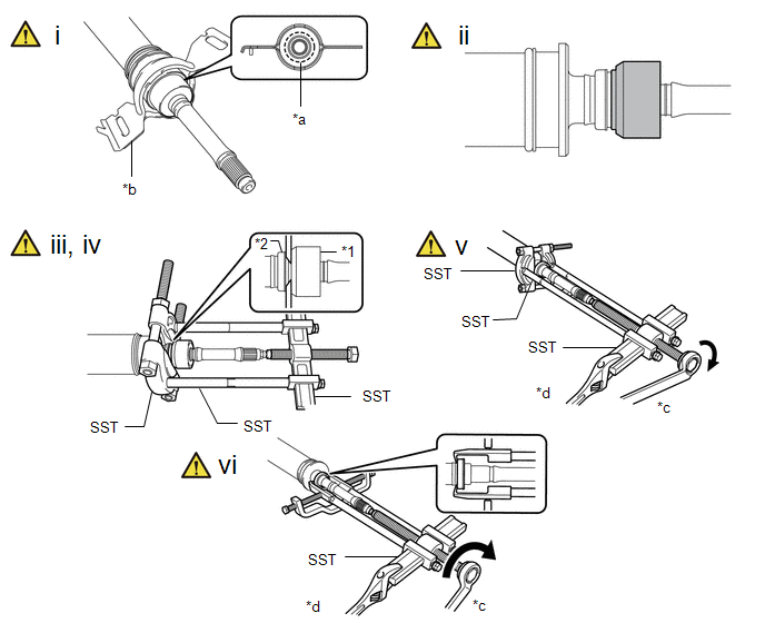
|
*1 |
Center Support Bearing |
*2 |
No. 1 Dust Deflector |
|
*a |
Cleavage site |
*b |
Bracket |
|
*c |
Turn |
*d |
Hold |
(1) Cut off the rubber portion of the center support bearing and remove the bracket.
(2) Remove any excess rubber so the center support bearing appears as shown in the illustration.
(3) Install SST as shown in the illustration.
SST: 09950-00020
SST: 09950-00040
SST: 09950-40011
09951-04020
09952-04010
09953-04020
09954-04020
09957-04010
NOTICE:
Securely install SST between the center support bearing and No. 1 dust deflector.
(4) Apply grease to the threaded area of the SST center bolt.
(5) Using SST, remove the center support bearing and flange from the front propeller shaft assembly.
SST: 09950-00020
SST: 09950-00040
SST: 09950-40011
09951-04020
09952-04010
09953-04020
09954-04020
09957-04010
HINT:
Perform this procedure with 2 or more people and prevent the propeller shaft from rotating.
(6) Using SST, remove the No. 1 dust deflector.
SST: 09950-40011
09951-04020
09952-04010
09953-04020
09954-04030
09955-04031
09957-04010
09958-04011


