Toyota Corolla Cross: Rear Wiper Motor Circuit
DESCRIPTION
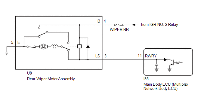
This circuit is the power source circuit for the rear wiper motor assembly.
WIRING DIAGRAM
CAUTION / NOTICE / HINT
NOTICE:
- Inspect the fuses of circuits related to this system before performing the following procedure.
- Before replacing the main body ECU (multiplex network body ECU), refer to Registration.*1
- for HEV Model:
Click here
.gif)
- for Gasoline Model:
Click here
- *1: w/ Smart Key System
- for HEV Model:
PROCEDURE
|
1. | PERFORM ACTIVE TEST USING GTS (REAR WIPER OPERATION) |
(a) Perform the Active Test according to the display on the GTS.
Body Electrical > Main Body > Active Test|
Tester Display | Measurement Item |
Control Range | Diagnostic Note |
|---|---|---|---|
|
Rear Wiper Operation | Function to operate the rear wiper motor assembly |
OFF or ON | - |
|
Tester Display |
|---|
| Rear Wiper Operation |
OK:
Rear wiper motor assembly operates normally.
| OK | .gif) | PROCEED TO NEXT SUSPECTED AREA SHOWN IN PROBLEM SYMPTOMS TABLE |
|
.gif)
| 2. |
INSPECT REAR WIPER MOTOR ASSEMBLY |
Click here
| NG | |
REPLACE REAR WIPER MOTOR ASSEMBLY |
|
| 3. |
CHECK HARNESS AND CONNECTOR (POWER SOURCE - REAR WIPER MOTOR ASSEMBLY) |
| (a) Measure the voltage according to the value(s) in the table below. Standard Voltage:
|
|
| NG | | REPAIR OR REPLACE HARNESS OR CONNECTOR |
|
| 4. |
CHECK HARNESS AND CONNECTOR (REAR WIPER MOTOR ASSEMBLY - BODY GROUND) |
(a) Measure the resistance according to the value(s) in the table below.
Standard Resistance:
|
Tester Connection | Condition |
Specified Condition |
|---|---|---|
|
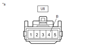
U8-5 (E) - Body Ground |
Always | Below 1 Ω |
| NG | | REPAIR OR REPLACE HARNESS OR CONNECTOR |
|
| 5. |
CHECK HARNESS AND CONNECTOR (REAR WIPER MOTOR ASSEMBLY - MAIN BODY ECU (MULTIPLEX NETWORK BODY ECU)) |
(a) Disconnect the I85 main body ECU (multiplex network body ECU) connector.
(b) Measure the resistance according to the value(s) in the table below.
Standard Resistance:
|
Tester Connection | Condition |
Specified Condition |
|---|---|---|
|
U8-3 (LS) - I85-11 (RWRY) |
Always | Below 1 Ω |
|
U8-3 (LS) or I85-11 (RWRY) - Body ground |
Always | 10 kΩ or higher |
| OK | | REPLACE MAIN BODY ECU (MULTIPLEX NETWORK BODY ECU) |
| NG | | REPAIR OR REPLACE HARNESS OR CONNECTOR |


