Toyota Corolla Cross Owners & Service Manuals

Toyota Corolla Cross: On-vehicle Inspection

ON-VEHICLE INSPECTION

PROCEDURE

1. INSPECT AIR CONDITIONER PRESSURE SENSOR

(a) Check the wire harness.

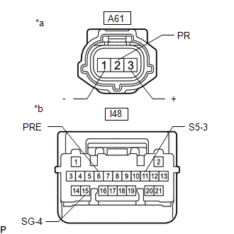
(1) Disconnect the A61 air conditioner pressure sensor connector.

(2) Disconnect the I48 air conditioning amplifier assembly connector.

(3) Measure the resistance according to the value(s) in the table below.

Standard Resistance:

Tester Connection

Condition

Specified Condition

A61-1 (-) - I48-15 (SG-4)

Always

Below 1 Ω

A61-2 (PR) - I48-6 (PRE)

Always

Below 1 Ω

A61-3 (+) - I48-11 (S5-3)

Always

Below 1 Ω

A61-1 (-) or I48-15 (SG-4) - Other terminals and body ground

Always

10 kΩ or higher

A61-2 (PR) or I48-6 (PRE) - Other terminals and body ground

Always

10 kΩ or higher

A61-3 (+) or I48-11 (S5-3) - Other terminals and body ground

Always

10 kΩ or higher

If the resistance is not as specified, repair or replace the wire harness.

*a

Front view of wire harness connector

(Air Conditioner Pressure Sensor)

*b

Front view of wire harness connector

(Air Conditioning Amplifier Assembly)

(4) Connect the I48 air conditioning amplifier assembly connector.

(5) Turn the ignition switch ON.

(6) Measure the voltage according to the value(s) in the table below.

Standard Voltage:

Tester Connection

Condition

Specified Condition

A61-3 (+) - Body ground

Ignition switch ON

4.75 to 5.25 V

If the voltage is not as specified, repair or replace the wire harness or replace air conditioning amplifier assembly.

*a

Front view of wire harness connector

(Air Conditioner Pressure Sensor)

(b) Check the air conditioner pressure sensor.

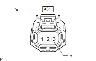
(1) Connect the A61 air conditioner pressure sensor connector.

(2) Install a manifold gauge set.

(3) Turn the A/C switch on.

(4) Measure the voltage according to the value(s) in the table below.
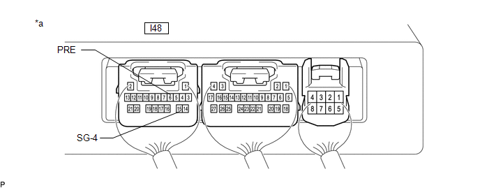
*a

Component with harness connected

(Air Conditioning Amplifier Assembly)

-

-

HINT:

Check from the rear of the connector while it is connected to the air conditioning amplifier assembly.

Standard Voltage:

Tester Connection

Condition

Specified Condition

I48-6 (PRE) - I48-15 (SG-4)

Refrigerant pressure: Normal pressure (less than 3025 kPa (30.8 kgf/cm2, 439 psi) and more than 176 kPa (1.8 kgf/cm2, 26 psi))

0.74 to 4.61 V

If the voltage is not as specified, replace the air conditioner pressure sensor.

    READ NEXT:

     Removal

    REMOVAL CAUTION / NOTICE / HINT COMPONENTS (REMOVAL) Procedure Part Name Code 1 RECOVER REFRIGERANT FROM REFRIGERATION SYSTEM - - -

     Installation

    INSTALLATION CAUTION / NOTICE / HINT COMPONENTS (INSTALLATION) Procedure Part Name Code 1 AIR CONDITIONER PRESSURE SENSOR 88719A - -

     Air Conditioning System (for Gasoline Model With Automatic Air Conditioning System)

    SEE MORE:

     Front Control Rear Air Outlet Damper Control Servo Motor Actuator Stuck Off (B13AB7F)

    DESCRIPTION The No. 2 air conditioning radiator damper servo sub-assembly sends pulse signals to inform the air conditioning amplifier assembly of the damper position. The air conditioning amplifier assembly activates the motor (normal or reverse) based on these signals to move the No. 2 air condi

     HV Battery High-voltage Line Circuit

    DESCRIPTION The cause of the malfunction may be the HV battery high-voltage line circuit. Check the continuity in the high-voltage line from the HV battery to the inverter. Check the connection condition and for an open circuit in the frame wire from the service plug grip, EV electric battery

    © 2020-2025 Copyright www.tcorollacross.com PT NL