Toyota Corolla Cross: On-vehicle Inspection
ON-VEHICLE INSPECTION
PROCEDURE
1. INSPECT AUTOMATIC LIGHT CONTROL SENSOR
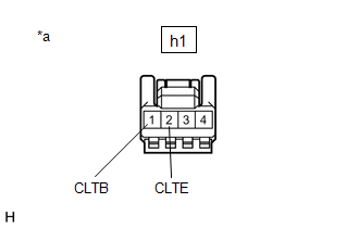
(a) Disconnect the h1 automatic light control sensor connector.
| (b) Measure the voltage and resistance according to the value(s) in the table below. Standard Voltage:
Standard Resistance:
If the result is not as specified, there may be a malfunction on the wire harness side. |
|
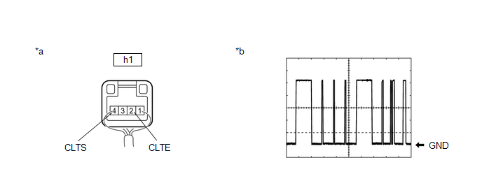
(c) Connect the h1 automatic light control sensor connector.
(d) Connect an oscilloscope to terminals h1-2 (CLTE) and h1-4 (CLTS) of the automatic light control sensor connector and check the waveform.
|
*a | Component with harness connected (Automatic Light Control Sensor) |
*b | Waveform |
OK:
|
Tester Connection | Condition |
Tool Setting | Specified Condition |
|---|---|---|---|
|
h1-2 (CLTE) - h1-4 (CLTS) |
Ignition switch on (IG) |
2 V/DIV., 10 ms./DIV. |
Pulse generation (See waveform) |
HINT:
The communication waveform changes according to the surrounding brightness.
If the result is not as specified, the automatic light control sensor may be malfunctioning.


