Toyota Corolla Cross: Installation
INSTALLATION
CAUTION / NOTICE / HINT
COMPONENTS (INSTALLATION)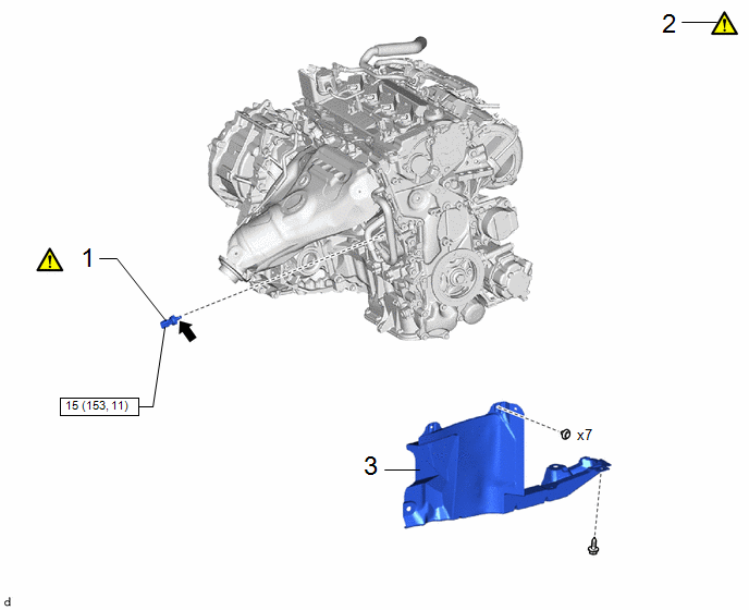
|
Procedure | Part Name Code |
.png) |
.png) |
 |
|---|---|---|---|---|---|
|
1 | OIL PRESSURE AND TEMPERATURE SENSOR |
89448D |
|
- | - |
|
2 | INSPECT FOR ENGINE OIL LEAK |
- |
|
- | - |
|
3 | REAR ENGINE UNDER COVER RH |
51443C | - |
- | - |
.png) |
N*m (kgf*cm, ft.*lbf): Specified torque |
.png) |
Adhesive 1344 |
|
★ | Precoated part |
- | - |
PROCEDURE
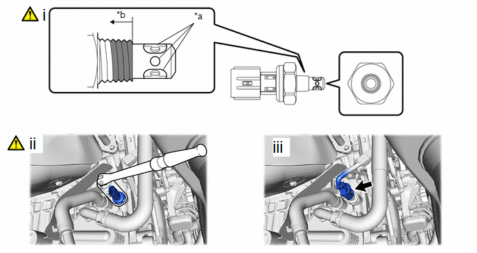
1. INSTALL OIL PRESSURE AND TEMPERATURE SENSOR
|
*a | Oil Inlet Port |
*b | 3 Threads or More |
 |
Adhesive Application Area |
- | - |
(1) Apply adhesive to the area shown in the illustration.
Adhesive:
Toyota Genuine Adhesive 1344, Three Bond 1344 or equivalent
NOTICE:
- Do not apply adhesive to the oil inlet port of the oil pressure and temperature sensor.
- Apply the adhesive to the first 3 threads or more of the oil pressure and temperature sensor.
- Apply adhesive to the entire circumference of the thread.
- To prevent contamination by foreign matter, install immediately after applying adhesive.
(2) Using a 24 mm deep socket wrench, install the oil pressure and temperature sensor.
Torque:
15 N·m {153 kgf·cm, 11 ft·lbf}
NOTICE:
Do not start the engine within 1 hour of installation.
(3) Connect the oil pressure and temperature sensor connector.
2. INSPECT FOR ENGINE OIL LEAK
|
|
Click here |
3. INSTALL REAR ENGINE UNDER COVER RH
Click here
.gif)


