Toyota Corolla Cross: Installation
INSTALLATION
CAUTION / NOTICE / HINT
COMPONENTS (INSTALLATION)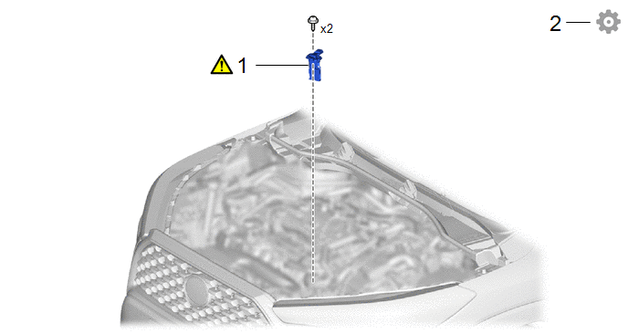
|
Procedure | Part Name Code |
.png) |
.png) |
 |
|---|---|---|---|---|---|
|
1 | MASS AIR FLOW METER SUB-ASSEMBLY |
22204 |
|
- | - |
|
2 | PERFORM INITIALIZATION |
- | - |
- |
|
PROCEDURE
1. INSTALL MASS AIR FLOW METER SUB-ASSEMBLY
|
|
HINT: Perform "Inspection After Repair" after replacing the mass air flow meter sub-assembly. Click here |
(1) Install the mass air flow meter sub-assembly to the air cleaner cap sub-assembly with the 2 screws.
NOTICE:
- If the mass air flow meter sub-assembly has been struck or dropped, replace it.
- If reusing the mass air flow meter sub-assembly, be sure to inspect the gasket.
- Make sure that the gasket is not cracked or moved out of place when installing the mass air flow meter sub-assembly.
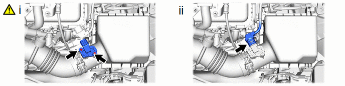
(2) Connect the mass air flow meter sub-assembly connector.
2. PERFORM INITIALIZATION
(a) Perform "Inspection After Repair" after replacing the mass air flow meter sub-assembly.
Click here .gif)


