Toyota Corolla Cross: Installation
INSTALLATION
CAUTION / NOTICE / HINT
COMPONENTS (INSTALLATION)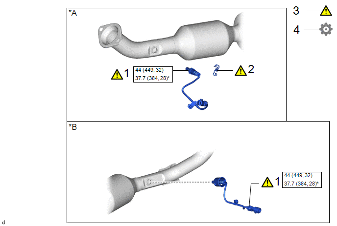
|
Procedure | Part Name Code |
.png) |
.png) |
 |
|---|---|---|---|---|---|
|
1 | NO. 2 AIR FUEL RATIO SENSOR |
89467C |
|
- | - |
|
2 | WIRING HARNESS CLAMP BRACKET |
82715W |
|
- | - |
|
3 | INSPECT FOR EXHAUST GAS LEAK |
- |
|
- | - |
|
4 | PERFORM INITIALIZATION |
- | - |
- |
|
|
*A | for 2WD: |
*B | for AWD: |
.png) |
N*m (kgf*cm, ft.*lbf): Specified torque |
* | For use with SST |
PROCEDURE
1. INSTALL NO. 2 AIR FUEL RATIO SENSOR
|
|
NOTICE:
|
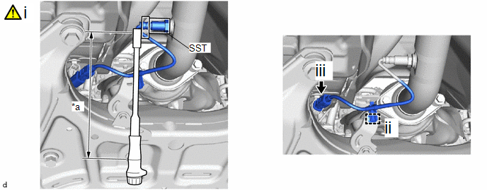
(a) for 2WD:
|
*a | Torque Wrench Fulcrum Length |
- | - |
(1) Using SST, install the No. 2 air fuel ratio sensor to the front exhaust pipe assembly (TWC: Rear Catalyst).
SST: 09224-00012
Torque:
Specified tightening torque :
44 N·m {449 kgf·cm, 32 ft·lbf}
HINT:
- Calculate the torque wrench reading when changing the fulcrum length of the torque wrench.
Click here
.gif)
- When using SST (fulcrum length of 30 mm (1.18 in.)) + torque wrench (fulcrum length of 180 mm (7.09 in.)):
37.7 N*m (384 kgf*cm, 28 ft.*lbf)
(2) Engage the wire harness clamp.
(3) Connect the heated oxygen sensor connector.
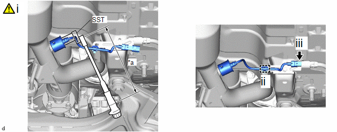
(b) for AWD:
|
*a | Torque Wrench Fulcrum Length |
- | - |
(1) Using SST, install the No. 2 air fuel ratio sensor to the front exhaust pipe assembly (TWC: Rear Catalyst).
SST: 09224-00012
Torque:
Specified tightening torque :
44 N·m {449 kgf·cm, 32 ft·lbf}
HINT:
- Calculate the torque wrench reading when changing the fulcrum length of the torque wrench.
Click here
- When using SST (fulcrum length of 30 mm (1.18 in.)) + torque wrench (fulcrum length of 180 mm (7.09 in.)):
37.7 N*m (384 kgf*cm, 28 ft.*lbf)
(2) Engage the wire harness clamp.
(3) Connect the heated oxygen sensor connector.
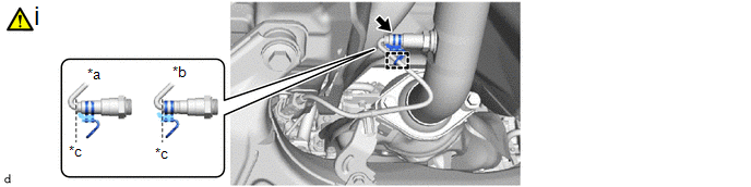
2. INSTALL WIRING HARNESS CLAMP BRACKET (for 2WD)
|
*a | Correct |
*b | Incorrect |
|
*c | Standard Position |
- | - |
(1) Install the wire harness clamp bracket to the No. 2 air fuel ratio sensor.
NOTICE:
Align the edge of the wire harness clamp bracket and No. 2 air fuel ratio sensor as shown in the illustration.
3. INSPECT FOR EXHAUST GAS LEAK
Click here
4. PERFORM INITIALIZATION
(a) Perform "Inspection After Repair" after replacing the air fuel ratio sensor.
Click here


