Toyota Corolla Cross Owners & Service Manuals

Toyota Corolla Cross: Installation

INSTALLATION

CAUTION / NOTICE / HINT

COMPONENTS (INSTALLATION)
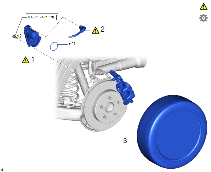
Procedure

Part Name Code

1

PARKING BRAKE ACTUATOR ASSEMBLY

46310B

-

-

2

NO. 2 PARKING BRAKE WIRE ASSEMBLY

890C0A

-

-

3

REAR WHEEL

-

-

-

-

*1

O-ring

-

-

Tightening torque for "Major areas involving basic vehicle performance such as moving/turning/stopping" : N*m (kgf*cm, ft.*lbf)

Non-reusable part

Lithium soap base glycol grease

-

-

CAUTION / NOTICE / HINT

HINT:

  • Use the same procedure for the RH side and LH side.
  • The following procedure is for the LH side.

PROCEDURE

1. INSTALL PARKING BRAKE ACTUATOR ASSEMBLY

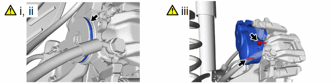
(1) Apply a light coat of lithium soap base glycol grease to a new O-ring.

(2) Install the O-ring to the rear disc brake cylinder assembly.

NOTICE:

Make sure to replace the O-ring with a new one when installing the parking brake actuator assembly.

(3) Using a 5 mm hexagon socket wrench, install the parking brake actuator assembly to the rear disc brake cylinder assembly with the 2 bolts.

Torque:

8.4 N·m {86 kgf·cm, 74 in·lbf}

2. CONNECT NO. 2 PARKING BRAKE WIRE ASSEMBLY

NOTICE:

  • Remove any dirt or foreign matter on and around the No. 2 parking brake wire assembly connector before performing this work.
  • Do not allow water, oil or dirt to enter the No. 2 parking brake wire assembly connector.

3. INSTALL REAR WHEEL

Click here

    READ NEXT:

     Electric Parking Brake Switch

     Removal

    REMOVAL CAUTION / NOTICE / HINT COMPONENTS (REMOVAL) Procedure Part Name Code 1 POSITION INDICATOR HOUSING ASSEMBLY

     Inspection

    INSPECTION PROCEDURE 1. INSPECT ELECTRIC PARKING BRAKE SWITCH ASSEMBLY (a) Check the resistance. (1) Measure the resistance according to the value(s) in the table below. Standard

    SEE MORE:

     DC/DC Converter Step Up Voltage Performance (P0CA300)

    DTC SUMMARY MALFUNCTION DESCRIPTION This DTC indicates that it has been detected that the VH voltage cannot be boosted as commanded due to malfunction of the boost converter system. The cause of this malfunction may be one of the following: Internal inverter malfunction Inverter with converte

     Problem Symptoms Table

    PROBLEM SYMPTOMS TABLE HINT: Use the table below to help determine the cause of problem symptoms. If multiple suspected areas are listed, the potential causes of the symptoms are listed in order of probability in the "Suspected Area" column of the table. Check each symptom by checking the susp

    © 2020-2025 Copyright www.tcorollacross.com PT NL