Toyota Corolla Cross: Inspection
INSPECTION
PROCEDURE
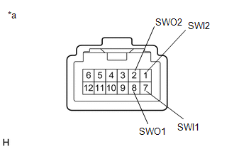
1. INSPECT ELECTRIC PARKING BRAKE SWITCH ASSEMBLY
(a) Check the resistance.
|
(1) Measure the resistance according to the value(s) in the
table below.
Standard Resistance:
|
Tester Connection
|
Condition
|
Specified Condition
|
|
7 (SWI1) - 8 (SWO1)
|
OFF (Release)
|
100 kΩ or higher
|
|
7 (SWI1) - 8 (SWO1)
|
ON (Lock)
|
10 Ω or less
|
|
7 (SWI1) - 8 (SWO1)
|
Switch not operated
|
100 kΩ or higher
|
|
7 (SWI1) - 1 (SWI2)
|
OFF (Release)
|
10 Ω or less
|
|
7 (SWI1) - 1 (SWI2)
|
ON (Lock)
|
10 Ω or less
|
|
7 (SWI1) - 1 (SWI2)
|
Switch not operated
|
100 kΩ or higher
|
|
7 (SWI1) - 2 (SWO2)
|
OFF (Release)
|
10 Ω or less
|
|
7 (SWI1) - 2 (SWO2)
|
ON (Lock)
|
100 kΩ or higher
|
|
7 (SWI1) - 2 (SWO2)
|
Switch not operated
|
10 Ω or less
|
|
1 (SWI2) - 8 (SWO1)
|
OFF (Release)
|
100 kΩ or higher
|
|
1 (SWI2) - 8 (SWO1)
|
ON (Lock)
|
10 Ω or less
|
|
1 (SWI2) - 8 (SWO1)
|
Switch not operated
|
10 Ω or less
|
|
1 (SWI2) - 2 (SWO2)
|
OFF (Release)
|
10 Ω or less
|
|
1 (SWI2) - 2 (SWO2)
|
ON (Lock)
|
100 kΩ or higher
|
|
1 (SWI2) - 2 (SWO2)
|
Switch not operated
|
100 kΩ or higher
|
|
 |
|
*a
|
Component without harness connected
(Electric Parking Brake Switch Assembly)
|
|
|
(2) If the result is not as specified, replace the electric parking
brake switch assembly.
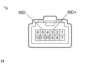
(b) Check the Illumination.
|
(1) Apply auxiliary battery voltage to the electric parking
brake switch assembly and check that the switch illuminates.
OK:
|
Tester Connection
|
Specified Condition
|
|
Auxiliary battery positive (+) → 3 (IND+)
Auxiliary battery negative (-) → 5 (IND-)
|
Illuminates
|
|
 |
|
*a
|
Component without harness connected
(Electric Parking Brake Switch Assembly)
|
|
|
(2) If the result is not as specified, replace the electric parking
brake switch assembly.
READ NEXT:
INSTALLATION
CAUTION / NOTICE / HINT
COMPONENTS (INSTALLATION)
Procedure
Part Name Code
1
COMBINATION SWITCH ASSEMBLY
PRECAUTION
TROUBLESHOOTING PRECAUTIONS
(a) When inspecting the rear brakes, disconnect the connector or
disconnect the cable from the negative (-) auxiliary battery terminal in order to
shut off
SEE MORE:
INSTALLATION CAUTION / NOTICE / HINT COMPONENTS (INSTALLTION)
Procedure Part Name Code
1 HORN BUTTON ASSEMBLY
45130
- -
2 CABLE TO NEGATIVE AUXILIARY BATTERY TERMINAL
- -
- -
3 INSPECT HORN BUTTON ASSEM
PROBLEM SYMPTOMS TABLE Stop and Start System
Symptom Suspected Area
Link
Stop and start system does not operate
Refer to "Stop and Start System does not Operate"
Refer to "Stop and Start System does not Operate (Battery Condition)"
Resta


