Toyota Corolla Cross: Generator Inverter Actuator Stuck Closed (P0A7A73)
DTC SUMMARY
MALFUNCTION DESCRIPTION
This DTC is stored when a short is detected in the inverter with converter assembly (generator inverter) or the hybrid vehicle transaxle assembly (generator (MG1)). The cause of this malfunction may be one of the following:
Internal inverter malfunction- Generator inverter internal circuit malfunction
- Open or short circuit
- Damage from iron particles or other foreign objects
DESCRIPTION
For a description of the inverter.
Click here .gif)
|
DTC No. | Detection Item |
DTC Detection Condition |
Trouble Area | MIL |
Warning Indicate | Note |
|---|---|---|---|---|---|---|
|
P0A7A73 | Generator Inverter Actuator Stuck Closed |
Current flow to any phase of the generator (MG1) exceeds the threshold after the generator inverter is shut down due to a DTC indicating a generator inverter malfunction (overheating, overcurrent or circuit malfunction) being stored. (1 trip detection logic) |
| Comes on |
Master Warning: Comes on |
SAE Code: P0A7A |
MONITOR DESCRIPTION
The motor generator control ECU monitors the generator inverter electric current. If the current exceeds the threshold for a specified period of time, the motor generator control ECU will illuminate the MIL and store a DTC.
MONITOR STRATEGY
|
Related DTCs | P0A7A (INF P0A7A73): GFIV detection (Short circuit malfunction) |
|
Required sensors/components | Generator inverter |
|
Frequency of operation | Continuous |
|
Duration | TMC's intellectual property |
|
MIL operation | 1 driving cycle |
|
Sequence of operation | None |
TYPICAL ENABLING CONDITIONS
|
The monitor will run whenever the following DTCs are not stored |
TMC's intellectual property |
|
Other conditions belong to TMC's intellectual property |
- |
TYPICAL MALFUNCTION THRESHOLDS
|
TMC's intellectual property | - |
COMPONENT OPERATING RANGE
|
Motor generator control ECU | DTC P0A7A (INF P0A7A73) is not detected |
CONFIRMATION DRIVING PATTERN
HINT:
- After repair has been completed, clear the DTC and then check that the vehicle has returned to normal by performing the following All Readiness check procedure.
Click here
- When clearing the permanent DTCs, refer to the "CLEAR PERMANENT DTC" procedure.
Click here
- Clear the DTCs (even if no DTCs are stored, perform the clear DTC procedure).
- Turn the ignition switch off and wait for 2 minutes or more.
- Turn the ignition switch to ON and wait for 5 seconds or more. [*1]
- Turn the ignition switch to ON (READY) and wait for 5 seconds or more. [*2]
HINT:
Check that there are no abnormalities (abnormal sounds, coolant leaks, etc.).
- Drive the vehicle for approximately 10 minutes mainly using the engine. [*3]
NOTICE:
As the state of charge of the HV battery may be low after driving in fail-safe mode, it will automatically be charged for 5 to 10 minutes with ignition switch ON (READY) after repairs have been performed.
HINT:
[*1] to [*3]: Normal judgment procedure.
The normal judgment procedure is used to complete DTC judgment and also used when clearing permanent DTCs.
- Enter the following menus: Powertrain / Motor Generator / Utility / All Readiness.
- Check the DTC judgment result.
HINT:
- If the judgment result shows NORMAL, the system is normal.
- If the judgment result shows ABNORMAL, the system has a malfunction.
- If the judgment result shows INCOMPLETE, perform the normal judgment procedure again.
WIRING DIAGRAM
Refer to the wiring diagram for the Generator High-voltage Circuit.
Click here
CAUTION / NOTICE / HINT
CAUTION:
Refer to the precautions before inspecting high voltage circuit.
Click here
NOTICE:
- After the ignition switch is turned off, there may be a waiting time before disconnecting the negative (-) auxiliary battery terminal.
Click here
- When disconnecting and reconnecting the auxiliary battery.
HINT:
When disconnecting and reconnecting the auxiliary battery, there is an automatic learning function that completes learning when the respective system is used.
Click here
- DTC P0A7A73 is stored after DTC P0A7A9E and/or P1C5F19 is stored. After troubleshooting and repairing the malfunction which caused DTC P0A7A73 to be stored, be sure to troubleshoot the other DTCs.
- Depending on the conditions in which the vehicle is being operated when a short circuit occurs in the inverter with converter assembly, the hybrid vehicle transaxle assembly may be affected. As this DTC is stored if a short circuit occurs in the inverter with converter assembly, it is necessary to perform a road test to check the hybrid vehicle transaxle assembly. If problems are found, replace the malfunctioning parts.
- After completing the repair, including the repair of previously output DTCs, drive the vehicle at a speed of approximately 40 km/h (25 mph) for 1 minute and check that DTC P0A92000 is not output. If DTC P0A92000 is output, replace the hybrid vehicle transaxle assembly.
HINT:
- P0A7A73 may be output as a result of the malfunctions indicated by the DTCs in table below.
- The chart above is listed in inspection order of priority.
- Check DTCs that are output at the same time by following the listed order. (The main cause of the malfunction can be determined without performing unnecessary inspections.)
|
Malfunction Content |
Relevant DTC | |
|---|---|---|
|
Insulation malfunction |
P1C7C49 | Hybrid/EV Battery Voltage System Isolation (A/C Area) Internal Electronic Failure |
|
P1C7D49 | Hybrid/EV Battery Voltage System Isolation (Hybrid/EV Battery Area) Internal Electronic Failure | |
|
P1C7E49 | Hybrid/EV Battery Voltage System Isolation (Transaxle Area) Internal Electronic Failure | |
|
P1C7F49 | Hybrid/EV Battery Voltage System Isolation (Direct Current Area) Internal Electronic Failure | |
|
P1C8049 | Hybrid/EV Battery Voltage System Isolation (Rear Motor Area) Internal Electronic Failure | |
PROCEDURE
|
1. | CHECK HYBRID VEHICLE TRANSAXLE ASSEMBLY (GENERATOR (MG1)) |
Click here
| NG | .gif) | GO TO STEP 3 |
|
.gif)
|
2. | REPLACE INVERTER WITH CONVERTER ASSEMBLY |
Click here
| NEXT | | GO TO STEP 12 |
|
3. | CHECK MOTOR CABLE (FOR MG1) |
Click here
| NG | | GO TO STEP 6 |
|
|
4. | REPLACE HYBRID VEHICLE TRANSAXLE ASSEMBLY |
Click here
|
|
5. | REPLACE INVERTER WITH CONVERTER ASSEMBLY |
Click here
| NEXT | | GO TO STEP 12 |
|
6. | CHECK HYBRID VEHICLE TRANSAXLE ASSEMBLY (GENERATOR (MG1)) |
CAUTION:
Be sure to wear insulated gloves.
(a) Check that the service plug grip is not installed.
NOTICE:
After removing the service plug grip, do not turn the ignition switch to ON (READY), unless instructed by the repair manual because this may cause a malfunction.
(b) Disconnect the motor cable from the hybrid vehicle transaxle assembly.
| (c) Check the generator (MG1) for an interphase short using a milliohmmeter. (1) Using a milliohmmeter, measure the resistance according to the value(s) in the table below. HINT: If the generator (MG1) temperature is high, the resistance will vary greatly from the specification. Therefore, measure the resistance at least 8 hours after the vehicle has been stopped. Standard Resistance:
HINT: To correct the variation of the measured resistance due to temperature, use the following formula to calculate the resistance at 20°C (68°F).
The calculation is based on the following:
|
|
(d) Check the difference in measured resistance values according to the table below.
Standard:
|
Inspection Item | Specified Condition |
|---|---|
|
[*1] - [*2] | -1.1 to 0.9 mΩ |
|
[*2] - [*3] | -1.2 to 0.8 mΩ |
|
[*3] - [*1] | -0.7 to 1.3 mΩ |
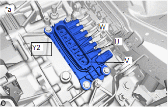
(e) Using a megohmmeter set to 500 V, measure the resistance according to the value(s) in the table below.
NOTICE:
Be sure to set the megohmmeter to 500 V when performing this test. Using a setting higher than 500 V can result in damage to the component being inspected.
Standard Resistance:
|
Tester Connection | Condition |
Specified Condition |
|---|---|---|
|
Y2-4 (W) - Body ground and shield ground |
Ignition switch off |
100 MΩ or higher |
|
Y2-5 (U) - Body ground and shield ground |
Ignition switch off |
100 MΩ or higher |
|
Y2-6 (V) - Body ground and shield ground |
Ignition switch off |
100 MΩ or higher |
(f) Connect the motor cable.
| NG | | GO TO STEP 9 |
|
|
7. | REPLACE MOTOR CABLE |
Click here
|
|
8. | REPLACE INVERTER WITH CONVERTER ASSEMBLY |
Click here
| NEXT | | GO TO STEP 12 |
|
9. | REPLACE MOTOR CABLE |
Click here
|
|
10. | REPLACE HYBRID VEHICLE TRANSAXLE ASSEMBLY |
Click here
|
|
11. | REPLACE INVERTER WITH CONVERTER ASSEMBLY |
Click here
|
|
12. | CHECK DTC OUTPUT (MOTOR GENERATOR) |
(a) Check the other DTCs that were output together with DTC P0A7A73.
Powertrain > Motor Generator > Trouble Codes|
Relevant DTC | |
|---|---|
|
P0A7A9E | Generator Inverter Stuck On |
|
P1C5F19 | Generator Inverter Circuit Current Above Threshold |
NOTICE:
DTC P0A7A73 is stored after DTC P0A7A9E and/or P1C5F19 is stored. After troubleshooting and repairing the malfunction which caused DTC P0A7A73 to be stored, be sure to troubleshoot the other DTCs.
| NEXT | | GO TO DTC CHART (MOTOR GENERATOR CONTROL SYSTEM) |


