Toyota Corolla Cross: Inspection
INSPECTION
PROCEDURE
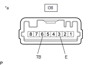
1. INSPECT HAZARD WARNING SIGNAL SWITCH ASSEMBLY
(a) Check that the resistance.
| (1) Measure the resistance according to the value(s) in the table below.
Standard Resistance: |
Tester Connection | Condition |
Specified Condition | |
I38-6 (TB) - I38-3 (E) |
Hazard warning switch off |
10 kΩ or higher | | I38-6 (TB) - I38-3 (E) |
Hazard warning switch on |
Below 50 Ω | If the result is not as specified, replace the hazard warning signal switch assembly. |
 |
|
*a | Component without harness connected
(Hazard Warning Signal Switch Assembly) | | |
(b) Check that the illumination lights.
| (1) Apply auxiliary battery voltage to the hazard warning signal switch assembly and check that the switch illumination lights comes on.
OK: |
Measurement Condition |
Condition | Specified Condition | |
I38-7 (ILL+) - Auxiliary battery positive (+) I38-2 (ILL-) - Auxiliary battery negative (-) |
Always | Switch illumination lights comes on |
If the result is not as specified, replace the hazard warning signal switch assembly. |
 |
|
*a | Component without harness connected
(Hazard Warning Signal Switch Assembly) | | |
READ NEXT:
INSTALLATION CAUTION / NOTICE / HINT COMPONENTS (INSTALLATION)
Procedure Part Name Code
1 HAZARD WARNING SIGNAL SWITCH ASSEMBLY
84380 -
- -
2 CE
REMOVAL CAUTION / NOTICE / HINT COMPONENTS (REMOVAL)
Procedure Part Name Code
1 FRONT BUMPER ASSEMBLY
- -
- -
2 WASHER INLET SUB-ASSEMBLY
8
SEE MORE:
INSPECTION PROCEDURE 1. INSPECT POWER WINDOW REGULATOR MOTOR ASSEMBLY LH
(a) Check the operation.
(1) Connect a positive (+) lead from the auxiliary battery to connector terminal N2-2 (B).
NOTICE: Do not connect a positive (+) lead from the auxiliary battery to any terminal other than termin
REMOVAL
CAUTION / NOTICE / HINT
COMPONENTS (REMOVAL)
Procedure
Part Name Code
1
PRECAUTION
-
-
-
2
ALIGN FRONT WHEELS FACING STRAIGHT AHEAD


