Toyota Corolla Cross: Camshaft Position Sensor "B" Bank 1 Circuit Short to Battery or Open (P036515)
DESCRIPTION
Refer to DTC P036511.
Click here
.gif)
|
DTC No. | Detection Item |
DTC Detection Condition | Trouble Area |
MIL | Note |
|---|---|---|---|---|---|
|
P036515 | Camshaft Position Sensor "B" Bank 1 Circuit Short to Battery or Open |
Diagnosis condition:
Abnormal condition:
Malfunction time:
Trip logic:
Detection conditions:
Sensors/components used for detection (Main):
Sensors/components used for detection (Related):
|
| Comes on |
|
Reference: Inspection using an oscilloscope.
Click here
MONITOR DESCRIPTION
2 seconds or more after the ignition switch has been turned ON, if the output voltage of the camshaft position sensor (for exhaust camshaft) is higher than 4.7 V for 4 seconds or more, the ECM determines that the camshaft position sensor (for exhaust camshaft) circuit is malfunctioning and illuminates the MIL and stores a DTC.
MONITOR STRATEGY
|
Related DTCs | P0368: Exhaust camshaft position sensor range check (high voltage) |
|
Required Sensors/Components (Main) | Camshaft position sensor (for exhaust camshaft) |
|
Required Sensors/Components (Related) |
Crankshaft position sensor |
|
Frequency of Operation | Continuous |
|
Duration | 4 seconds |
|
MIL Operation | Immediate |
|
Sequence of Operation | None |
TYPICAL ENABLING CONDITIONS
|
All of the following conditions are met |
- |
| Starter |
Off |
| Ignition switch |
ON |
| Time after ignition switch off to ON |
2 seconds or more |
|
Auxiliary battery voltage |
8 V or higher |
|
Exhaust camshaft position sensor verify pulse input fail (P0365) (Pending / MIL) |
Not detected |
TYPICAL MALFUNCTION THRESHOLDS
|
Exhaust camshaft position sensor voltage | Higher than 4.7 V |
CONFIRMATION DRIVING PATTERN
Refer to DTC P036511.
Click here
WIRING DIAGRAM
Refer to DTC P036511.
Click here
CAUTION / NOTICE / HINT
HINT:
Read Freeze Frame Data using the GTS. The ECM records vehicle and driving condition information as Freeze Frame Data the moment a DTC is stored. When troubleshooting, Freeze Frame Data can help determine if the vehicle was moving or stationary, if the engine was warmed up or not, if the air fuel ratio was lean or rich, and other data from the time the malfunction occurred.
PROCEDURE
| 1. |
CHECK TERMINAL VOLTAGE (CAMSHAFT POSITION SENSOR (FOR EXHAUST CAMSHAFT)) |
|
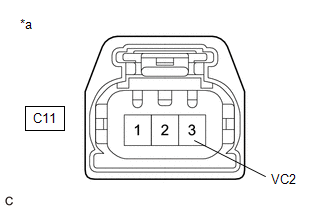
*a | Front view of wire harness connector (to Camshaft Position Sensor (for Exhaust Camshaft)) |
HINT:
Make sure that the connector is properly connected. If it is not, securely connect it and check for DTCs again.
(a) Disconnect the camshaft position sensor (for exhaust camshaft) connector.
(b) Turn the ignition switch to ON.
(c) Measure the voltage according to the value(s) in the table below.
Standard Voltage:
|
Tester Connection | Condition |
Specified Condition |
|---|---|---|
|
C11-3 (VC2) - Body ground |
Ignition switch ON | 4.5 to 5.5 V |
|
Result | Proceed to |
|---|---|
|
Higher than 5.5 V | A |
|
4.5 to 5.5 V | B |
|
Below 4.5 V | C |
| B |
.gif) | GO TO STEP 3 |
| C |
| GO TO STEP 10 |
|
.gif)
| 2. |
CHECK HARNESS AND CONNECTOR (CAMSHAFT POSITION SENSOR (FOR EXHAUST CAMSHAFT) - ECM) |
(a) Disconnect the camshaft position sensor (for exhaust camshaft) connector.
(b) Disconnect the ECM connector.
(c) Measure the resistance according to the value(s) in the table below.
Standard Resistance:
|
Tester Connection | Condition |
Specified Condition |
|---|---|---|
|
C11-3 (VC2) or C76-113 (VCE1) - Other terminals |
Always | 10 kΩ or higher |
| OK | | REPLACE ECM
|
| NG | | REPAIR OR REPLACE HARNESS OR CONNECTOR |
| 3. |
CHECK TERMINAL VOLTAGE (CAMSHAFT POSITION SENSOR (FOR EXHAUST CAMSHAFT)) |
|
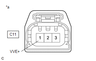
*a | Front view of wire harness connector (to Camshaft Position Sensor (for Exhaust Camshaft)) |
(a) Disconnect the camshaft position sensor (for exhaust camshaft) connector.
(b) Turn the ignition switch to ON.
(c) Measure the voltage according to the value(s) in the table below.
Standard Voltage:
|
Tester Connection | Condition |
Specified Condition |
|---|---|---|
|
C11-1 (VVE+) - Body ground |
Ignition switch ON | 3.0 to 5.0 V |
|
Result | Proceed to |
|---|---|
|
Higher than 5.0 V | A |
|
3.0 to 5.0 V | B |
|
Below 3.0 V | C |
| B |
| GO TO STEP 5 |
| C |
| GO TO STEP 9 |
|
| 4. |
CHECK HARNESS AND CONNECTOR (CAMSHAFT POSITION SENSOR (FOR EXHAUST CAMSHAFT) - ECM) |
(a) Disconnect the camshaft position sensor (for exhaust camshaft) connector.
(b) Disconnect the ECM connector.
(c) Measure the resistance according to the value(s) in the table below.
Standard Resistance:
|
Tester Connection | Condition |
Specified Condition |
|---|---|---|
|
C11-1 (VVE+) or C76-91 (EV1+) - Other terminals |
Always | 10 kΩ or higher |
| OK | | REPLACE ECM
|
| NG | | REPAIR OR REPLACE HARNESS OR CONNECTOR |
| 5. |
CHECK HARNESS AND CONNECTOR (CAMSHAFT POSITION SENSOR (FOR EXHAUST CAMSHAFT) - BODY GROUND) |
(a) Disconnect the camshaft position sensor (for exhaust camshaft) connector.
(b) Measure the resistance according to the value(s) in the table below.
Standard Resistance:
|
Tester Connection | Condition |
Specified Condition |
|---|---|---|
|
C11-2 (VVE-) - Body ground |
Always | Below 1 Ω |
| NG | | GO TO STEP 8 |
|
| 6. |
CHECK INTERNAL RESISTANCE (ECM) |
(a) Turn the ignition switch off.
(b) Disconnect the camshaft position sensor (for exhaust camshaft) connector.
(c) Measure the resistance according to the value(s) in the table below.
Standard Resistance:
|
Tester Connection | Condition |
Specified Condition |
|---|---|---|
|
C11-3 (VC2) - C11-1 (VVE+) |
Ignition switch off | 1.425 to 1.575 kΩ |
HINT:
As voltage is still supplied to the ECM after the ignition switch is turned off, this check cannot be performed correctly during the shut-down process.
| OK | | REPLACE CAMSHAFT POSITION SENSOR (FOR EXHAUST CAMSHAFT) |
|
| 7. |
CHECK HARNESS AND CONNECTOR (CAMSHAFT POSITION SENSOR (FOR EXHAUST CAMSHAFT) - ECM) |
(a) Disconnect the camshaft position sensor (for exhaust camshaft) connector.
(b) Disconnect the ECM connector.
(c) Measure the resistance according to the value(s) in the table below.
Standard Resistance:
|
Tester Connection | Condition |
Specified Condition |
|---|---|---|
|
C11-3 (VC2) - C11-1 (VVE+) or C76-113 (VCE1) - C76-91 (EV1+) |
Always | 10 kΩ or higher |
| OK | | REPLACE ECM
|
| NG | | REPAIR OR REPLACE HARNESS OR CONNECTOR |
| 8. |
CHECK HARNESS AND CONNECTOR (CAMSHAFT POSITION SENSOR (FOR EXHAUST CAMSHAFT) - ECM) |
(a) Disconnect the camshaft position sensor (for exhaust camshaft) connector.
(b) Disconnect the ECM connector.
(c) Measure the resistance according to the value(s) in the table below.
Standard Resistance:
|
Tester Connection | Condition |
Specified Condition |
|---|---|---|
|
C11-2 (VVE-) - C76-114 (EV1-) |
Always | Below 1 Ω |
| OK | | REPLACE ECM
|
| NG | | REPAIR OR REPLACE HARNESS OR CONNECTOR |
| 9. |
CHECK HARNESS AND CONNECTOR (CAMSHAFT POSITION SENSOR (FOR EXHAUST CAMSHAFT) - ECM) |
(a) Disconnect the camshaft position sensor (for exhaust camshaft) connector.
(b) Disconnect the ECM connector.
(c) Measure the resistance according to the value(s) in the table below.
Standard Resistance:
|
Tester Connection | Condition |
Specified Condition |
|---|---|---|
|
C11-1 (VVE+) - C76-91 (EV1+) |
Always | Below 1 Ω |
| OK | | REPLACE ECM
|
| NG | | REPAIR OR REPLACE HARNESS OR CONNECTOR |
| 10. |
CHECK HARNESS AND CONNECTOR (CAMSHAFT POSITION SENSOR (FOR EXHAUST CAMSHAFT) - ECM) |
(a) Disconnect the camshaft position sensor (for exhaust camshaft) connector.
(b) Disconnect the ECM connector.
(c) Measure the resistance according to the value(s) in the table below.
Standard Resistance:
|
Tester Connection | Condition |
Specified Condition |
|---|---|---|
|
C11-3 (VC2) - C76-113 (VCE1) |
Always | Below 1 Ω |
| OK | | REPLACE ECM
|
| NG | | REPAIR OR REPLACE HARNESS OR CONNECTOR |


