Toyota Corolla Cross: Reassembly
REASSEMBLY
CAUTION / NOTICE / HINT
COMPONENTS (REASSEMBLY)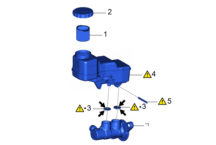
|
Procedure |
Part Name Code |
.png) |
.png) |
.png) |
|
|---|---|---|---|---|---|
|
1 |
BRAKE MASTER CYLINDER RESERVOIR STRAINER |
- |
- |
- |
- |
|
2 |
BRAKE MASTER CYLINDER RESERVOIR FILLER CAP |
- |
- |
- |
- |
|
3 |
MASTER CYLINDER RESERVOIR GROMMET |
- |
|
- |
- |
|
4 |
BRAKE MASTER CYLINDER RESERVOIR ASSEMBLY |
47220D |
|
- |
- |
|
5 |
BRAKE MASTER CYLINDER STRAIGHT PIN |
- |
|
- |
- |
.gif)
|
*1 |
BRAKE MASTER CYLINDER SUB-ASSEMBLY |
- |
- |
|
● |
Non-reusable part |
.png) |
Lithium soap base glycol grease |
PROCEDURE
1. INSTALL BRAKE MASTER CYLINDER RESERVOIR STRAINER
2. INSTALL BRAKE MASTER CYLINDER RESERVOIR FILLER CAP
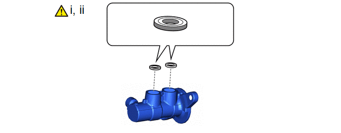
3. INSTALL MASTER CYLINDER RESERVOIR GROMMET
 |
Lithium Soap Base Glycol Grease |
- |
- |
(1) Apply a light layer of lithium soap base glycol grease to the entire circumference of 2 new master cylinder reservoir grommets.
(2) Install the 2 master cylinder reservoir grommets to the brake master cylinder body.
4. INSTALL BRAKE MASTER CYLINDER RESERVOIR ASSEMBLY

(1) Secure the brake master cylinder body in a vise.
NOTICE:
Place aluminum plates on the vise to prevent damage to the brake master cylinder body.
(2) Install the brake master cylinder reservoir assembly to the brake master cylinder body.
NOTICE:
Do not drop the brake master cylinder reservoir assembly.
5. INSTALL BRAKE MASTER CYLINDER STRAIGHT PIN

(1) Using a 5 mm pin punch and a hammer, tap in the brake master cylinder ring pin to secure the brake master cylinder reservoir assembly.


