Toyota Corolla Cross: M20a-fks Drive Belt
Removal
REMOVAL
CAUTION / NOTICE / HINT
COMPONENTS (REMOVAL)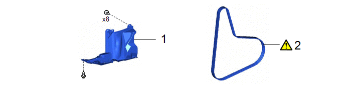
|
Procedure |
Part Name Code |
.png) |
.png) |
.png) |
|
|---|---|---|---|---|---|
|
1 |
REAR ENGINE UNDER COVER RH |
51443C |
- |
- |
- |
|
2 |
V-RIBBED BELT |
16361A |
|
- |
- |
.gif)
PROCEDURE
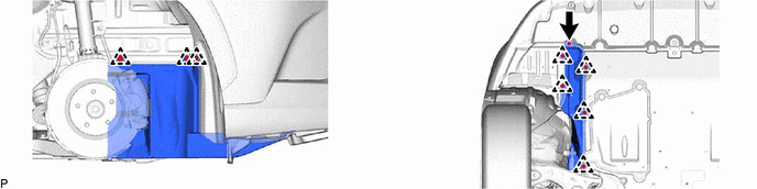
1. REMOVE REAR ENGINE UNDER COVER RH
2. REMOVE V-RIBBED BELT
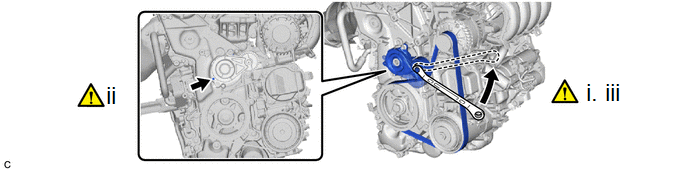
(1) Release the V-ribbed belt tension by turning the V-ribbed belt tensioner assembly counterclockwise.
(2) Turn the V-ribbed belt tensioner assembly counterclockwise to align its holes, and then insert a 5 mm hexagon wrench to secure the V-ribbed belt tensioner assembly.
(3) Remove the V-ribbed belt.
Installation
INSTALLATION
CAUTION / NOTICE / HINT
COMPONENTS (INSTALLATION)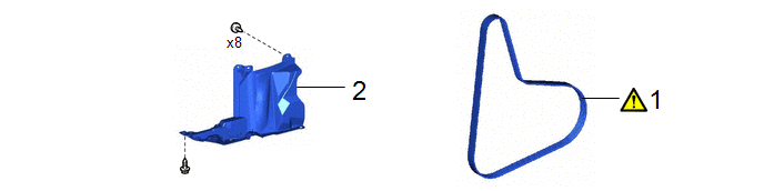
|
Procedure |
Part Name Code |
.png) |
.png) |
.png) |
|
|---|---|---|---|---|---|
|
1 |
V-RIBBED BELT |
16361A |
|
- |
- |
|
2 |
REAR ENGINE UNDER COVER RH |
51443C |
- |
- |
- |
.gif)
PROCEDURE
1. INSTALL V-RIBBED BELT
|
|
HINT: When reusing the V-ribbed belt, check the ribs and back of the V-ribbed belt for wear and cracks. If wear or a crack that reaches the core (at more than 1 point) is found, replace the V-ribbed belt. |
|
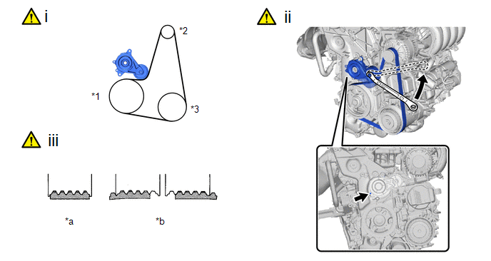
*1 |
Crankshaft Pulley Assembly |
*2 |
Generator Assembly |
|
*3 |
Compressor Assembly with Pulley |
- |
- |
|
*a |
Correct |
*b |
Incorrect |
(1) Set the V-ribbed belt onto each pulley as shown in the illustration.
(2) Turn the V-ribbed belt tensioner assembly clockwise and remove the 5 mm hexagon wrench.
(3) After installing the V-ribbed belt, check that it fits properly in the ribbed grooves. Confirm that the V-ribbed belt has not slipped out of the grooves on the bottom of the pulley by hand.
2. INSTALL REAR ENGINE UNDER COVER RH


