Toyota Corolla Cross: Automatic High Beam Switch Circuit
DESCRIPTION
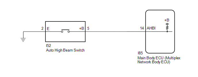
The main body ECU (multiplex network body ECU) detects the ON/OFF signal of the automatic high beam switch (turn signal switch).
WIRING DIAGRAM
CAUTION / NOTICE / HINT
NOTICE:
Before replacing the main body ECU (multiplex network body ECU), refer to Registration.*1
for HEV Model: Click here
.gif)
for Gasoline Model: Click here
- *1: w/ Smart Key System
PROCEDURE
|
1. |
READ VALUE USING GTS |
(a) Read the Data List according to the display on the GTS.
Body Electrical > Main Body > Data List|
Tester Display |
Measurement Item |
Range |
Normal Condition |
Diagnostic Note |
|---|---|---|---|---|
|
Auto High Beam Main Switch |
Adaptive high beam switch signal |
OFF or ON |
OFF: Adaptive high beam switch not pressed ON: Adaptive high beam switch pressed |
- |
|
Tester Display |
|---|
|
Auto High Beam Main Switch |
OK:
Normal conditions listed above are displayed.
| OK | .gif)
|
PROCEED TO NEXT SUSPECTED AREA SHOWN IN PROBLEM SYMPTOMS TABLE |
|
.gif)
|
2. |
INSPECT AUTO HIGH BEAM SWITCH |
Click here
| NG |
|
REPLACE AUTO HIGH BEAM SWITCH |
|
|
3. |
INSPECT HARNESS AND CONNECTOR (AUTO HIGH BEAM SWITCH - MAIN BODY ECU (MULTIPLEX NETWORK BODY ECU) AND BODY GROUND) |
(a) Disconnect the I85 main body ECU (multiplex network body ECU) connector.
(b) Measure the resistance according to the value(s) in the table below.
Standard Resistance:
|
Tester Connection |
Condition |
Specified Condition |
|---|---|---|
|
I52-5 (+B) -I85-14 (AHBI) |
Always |
Below 1 Ω |
|
I52-5 (+B) - Body ground |
Always |
10 kΩ or higher |
|
I52-2 (E) - Body ground |
Always |
Below 1 Ω |
| OK |
|
REPLACE MAIN BODY ECU (MULTIPLEX NETWORK BODY ECU) |
| NG |
|
REPAIR OR REPLACE HARNESS OR CONNECTOR |


