Toyota Corolla Cross: Adjustment
ADJUSTMENT
PROCEDURE
1. INSPECT AND ADJUST BRAKE PEDAL HEIGHT
(a) Remove the front door scuff plate LH.
Click here .gif)
(b) Remove the cowl side trim sub-assembly LH.
Click here
(c) Turn back the front floor carpet assembly.
(d) Check the brake pedal height.
NOTICE:
- Inspect and adjust the brake pedal height with the floor carpet folded back.
- When performing the measurement, make sure that the measuring device is contacting the surface of the dash panel insulator assembly clip.
(1) Measure the shortest distance between the brake pedal pad surface and dash panel insulator assembly clip.
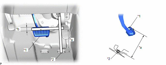
|
*1 |
Brake Pedal Pad |
*2 |
Dash Panel Insulator Assembly Clip |
|
*a |
Brake Pedal Height |
*b |
30 mm (1.18 in.) |
Brake Pedal Height from Dash Panel Insulator Assembly Clip:
184.4 to 196.4 mm (7.26 to 7.73 in.)
- If the brake pedal height is not as specified, inspect and adjust the push rod length according to the procedure below.
(e) Adjust the push rod length.
|
(1) Remove the stop light switch assembly. Click here |
|
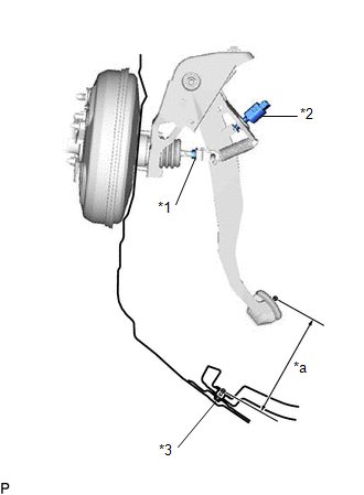
(2) Loosen the lock nut.
(3) Adjust the brake pedal height by turning the push rod.
Brake Pedal Height from Dash Panel Insulator Assembly Clip:
184.4 to 196.4 mm (7.26 to 7.73 in.)
(4) Tighten the lock nut.
Torque:
26 N·m {265 kgf·cm, 19 ft·lbf}
(5) Install the stop light switch assembly.
Click here
(f) Install the front floor carpet assembly to its original position.
(g) Install the cowl side trim sub-assembly LH.
(h) Install the front door scuff plate LH.
2. INSPECT BRAKE PEDAL FREE PLAY
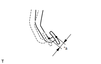
(a) Stop the engine and firmly depress the brake pedal several times until no vacuum is left in the brake booster assembly.
|
(b) Depress the brake pedal until a slight resistance is felt. Measure the distance as shown in the illustration. Brake Pedal Free Play: 1.0 to 6.0 mm (0.0394 to 0.236 in.) HINT:
|
|
3. INSPECT BRAKE PEDAL RESERVE DISTANCE
(a) With the engine running, depress the brake pedal and measure the brake pedal reserve distance.
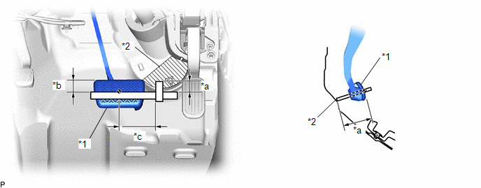
|
*1 |
Brake Pedal Pad |
*2 |
Column Hole Cover Silencer Sheet |
|
*a |
Brake Pedal Reserve Distance |
*b |
30 mm (1.18 in.) |
|
*c |
60 mm (2.36 in.) |
- |
- |
.png) |
Measuring Plane of Column Hole Cover Silencer Sheet |
- |
- |
Brake Pedal Reserve Distance from Column Hole Cover Silencer Sheet at 300 N (31 kgf, 67.4 lbf):
124 mm (4.88 in.) or more


