Toyota Corolla Cross: XM Tuner Antenna Circuit Short to Ground (B15FE11,B15FE13)
DESCRIPTION
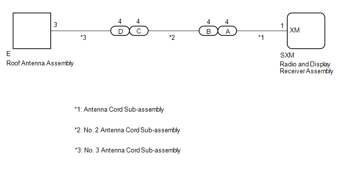
These DTCs are stored when a malfunction occurs in the XM antenna which is connected to the radio and display receiver assembly.
|
DTC No. |
Detection Item |
DTC Detection Condition |
Trouble Area |
DTC Output from |
Priority |
|---|---|---|---|---|---|
|
B15FE11 |
XM Tuner Antenna Circuit Short to Ground |
The XM antenna is not connected. (2 trip detection logic) |
|
Navigation System |
A |
|
B15FE13 |
XM Tuner Antenna Circuit Open |
A short occurs in the XM antenna. (2 trip detection logic) |
|
Navigation System |
A |
WIRING DIAGRAM
CAUTION / NOTICE / HINT
NOTICE:
Depending on the parts that are replaced during vehicle inspection or maintenance, performing initialization, registration or calibration may be needed.
Click here .gif)
PROCEDURE
|
1. |
CHECK CONNECTION OF ROOF ANTENNA ASSEMBLY CABLE |
(a) Check if the roof antenna assembly cable is securely connected to the radio and display receiver assembly.
OK:
Roof antenna assembly cable is securely connected.
| NG | .gif)
|
SECURELY CONNECT ROOF ANTENNA ASSEMBLY CABLE |
|
.gif)
|
2. |
CHECK ANTENNA CORD SUB-ASSEMBLY |
(a) Disconnect the antenna connector from the radio and display receiver assembly.
|
(b) Disconnect the antenna connector from the No. 2 antenna cord sub-assembly. |
|
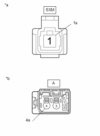
(c) Measure the resistance according to the value(s) in the table below.
Standard Resistance:
|
Tester Connection |
Condition |
Specified Condition |
|---|---|---|
|
SXM-1 (XM) - A-4 |
Always |
Below 1 Ω |
|
SXM-1a - A-4a |
Always |
Below 1 Ω |
|
SXM-1 (XM) - Body ground |
Always |
10 kΩ or higher |
|
SXM-1a - Body ground |
Always |
10 kΩ or higher |
| NG |
|
REPLACE ANTENNA CORD SUB-ASSEMBLY |
|
|
3. |
CHECK NO. 2 ANTENNA CORD SUB-ASSEMBLY |
(a) Disconnect the antenna connector from the antenna cord sub-assembly.
|
(b) Disconnect the antenna connector from the No. 3 antenna cord sub-assembly. |
|
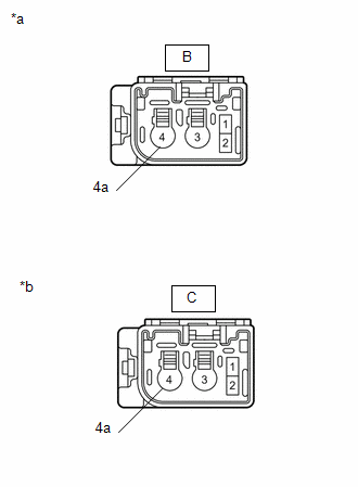
(c) Measure the resistance according to the value(s) in the table below.
Standard Resistance:
|
Tester Connection |
Condition |
Specified Condition |
|---|---|---|
|
B-4 - C-4 |
Always |
Below 1 Ω |
|
B-4a - C-4a |
Always |
Below 1 Ω |
|
B-4 - Body ground |
Always |
10 kΩ or higher |
|
B-4a - Body ground |
Always |
10 kΩ or higher |
| NG |
|
REPLACE NO. 2 ANTENNA CORD SUB-ASSEMBLY |
|
|
4. |
CHECK NO. 3 ANTENNA CORD SUB-ASSEMBLY |
(a) Disconnect the antenna connector from the No. 2 antenna cord sub-assembly.
|
(b) Disconnect the antenna connector from the roof antenna assembly. |
|
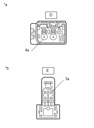
(c) Measure the resistance according to the value(s) in the table below.
Standard Resistance:
|
Tester Connection |
Condition |
Specified Condition |
|---|---|---|
|
D-4 - E-3 |
Always |
Below 1 Ω |
|
D-4a - E-3a |
Always |
Below 1 Ω |
|
D-4 - Body ground |
Always |
10 kΩ or higher |
|
D-4a - Body ground |
Always |
10 kΩ or higher |
| NG |
|
REPLACE NO. 3 ANTENNA CORD SUB-ASSEMBLY |
|
|
5. |
CHECK ROOF ANTENNA ASSEMBLY |
(a) Replace the roof antenna assembly with a new or known good one and check if the same problem occurs again.
Click here
|
|
6. |
CLEAR DTC |
(a) Clear the DTCs.
Body Electrical > Navigation System > Clear DTCs
|
|
7. |
CHECK FOR DTC |
(a) Turn the ignition switch off.
(b) Recheck for DTCs and check that no DTCs are output.
Body Electrical > Navigation System > Trouble Codes|
Result |
Proceed to |
|---|---|
|
DTCs are not output |
A |
|
DTCs are output |
B |
| A |
|
END (ROOF ANTENNA ASSEMBLY IS DEFECTIVE) |
| B |
|
REPLACE RADIO & DISPLAY RECEIVER ASSEMBLY |


