Toyota Corolla Cross: Front Right Speaker Cable Actuator Stuck (B1ACA71)
DESCRIPTION
This DTC is stored when the stereo component amplifier assembly detects an open in the front speaker RH circuit by energizing the speaker line.
|
DTC No. |
Detection Item |
DTC Detection Condition |
Trouble Area |
DTC Output from |
Priority |
|---|---|---|---|---|---|
|
B1ACA71 |
Front Right Speaker Cable Actuator Stuck |
Open in the front speaker RH circuit is detected. (1 trip detection logic) |
|
Navigation System |
A |
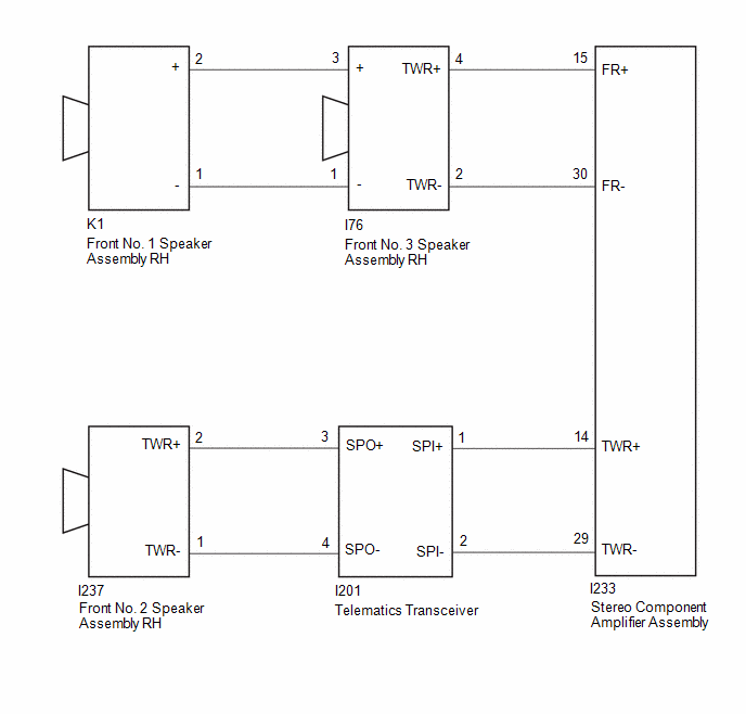
WIRING DIAGRAM
CAUTION / NOTICE / HINT
NOTICE:
- When replacing the telematics transceiver, make sure to replace it with a new one.
- Depending on the parts that are replaced during vehicle inspection or
maintenance, performing initialization, registration or calibration may
be needed.
Click here
.gif)
PROCEDURE
|
1. |
CHECK HARNESS AND CONNECTOR (STEREO COMPONENT AMPLIFIER ASSEMBLY - FRONT NO. 3 SPEAKER ASSEMBLY RH, TELEMATICS TRANSCEIVER) |
(a) Disconnect the I233 stereo component amplifier assembly connector.
(b) Disconnect the I76 front No. 3 speaker assembly RH connector.
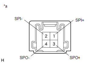
(c) Disconnect the I201 telematics transceiver connector.
(d) Measure the resistance according to the value(s) in the table below.
Standard Resistance:
|
Tester Connection |
Condition |
Specified Condition |
|---|---|---|
|
I233-15 (FR+) - I76-4 (+TW) |
Always |
Below 1 Ω |
|
I233-14 (TWR+) - I201-1 (SPI+) |
Always |
Below 1 Ω |
|
I233-30 (FR-) - I76-2 (-TW) |
Always |
Below 1 Ω |
|
I233-29 (TWR-) - I201-2 (SPI-) |
Always |
Below 1 Ω |
| NG | .gif)
|
REPAIR OR REPLACE HARNESS AND CONNECTOR |
|
.gif)
|
2. |
CHECK HARNESS AND CONNECTOR (FRONT NO. 1 SPEAKER ASSEMBLY RH - FRONT NO. 3 SPEAKER ASSEMBLY RH) |
(a) Disconnect the K1 front No. 1 speaker assembly RH connector.
(b) Disconnect the I76 front No. 3 speaker assembly RH connector.
(c) Measure the resistance according to the value(s) in the table below.
Standard Resistance:
|
Tester Connection |
Condition |
Specified Condition |
|---|---|---|
|
K1-2 (+) - I76-3 (+) |
Always |
Below 1 Ω |
|
K1-1 (-) - I76-1 (-) |
Always |
Below 1 Ω |
| NG |
|
REPAIR OR REPLACE HARNESS AND CONNECTOR |
|
|
3. |
CHECK HARNESS AND CONNECTOR (FRONT NO. 2 SPEAKER ASSEMBLY RH - TELEMATICS TRANSCEIVER) |
(a) Disconnect the I237 front No. 2 speaker assembly RH connector.
(b) Disconnect the I201 telematics transceiver connector.
(c) Measure the resistance according to the value(s) in the table below.
Standard Resistance:
|
Tester Connection |
Condition |
Specified Condition |
|---|---|---|
|
I237-2 (TWR+) - I201-3 (SPO+) |
Always |
Below 1 Ω |
|
I237-1 (TWR-) - I201-4 (SPO-) |
Always |
Below 1 Ω |
| NG |
|
REPAIR OR REPLACE HARNESS AND CONNECTOR |
|
|
4. |
INSPECT FRONT NO. 1 SPEAKER ASSEMBLY RH |
Click here
| NG |
|
REPLACE FRONT NO. 1 SPEAKER ASSEMBLY RH |
|
|
5. |
INSPECT FRONT NO. 2 SPEAKER ASSEMBLY RH |
Click here
| NG |
|
REPLACE FRONT NO. 2 SPEAKER ASSEMBLY RH |
|
|
6. |
INSPECT FRONT NO. 3 SPEAKER ASSEMBLY RH |
Click here
| NG |
|
REPLACE FRONT NO. 3 SPEAKER ASSEMBLY RH |
|
|
7. |
INSPECT TELEMATICS TRANSCEIVER |
(a) Disconnect the telematics transceiver connector.
|
(b) Measure the resistance according to the value(s) in the table below. Standard Resistance:
|
|
| OK |
|
REPLACE STEREO COMPONENT AMPLIFIER ASSEMBLY |
| NG |
|
REPLACE TELEMATICS TRANSCEIVER |


