Toyota Corolla Cross: Windshield Deicer Switch
Removal
REMOVAL
CAUTION / NOTICE / HINT
COMPONENTS (REMOVAL)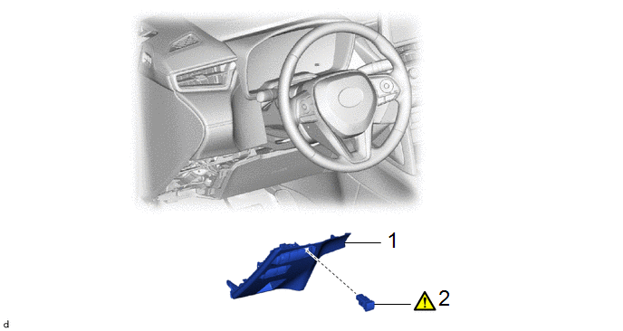
|
Procedure | Part Name Code |
.png) |
.png) |
 |
|---|---|---|---|---|---|
|
1 | LOWER NO.1 INSTRUMENT PANEL FINISH PANEL |
55432D | - |
- | - |
|
2 | FRONT WIPER DEICER SWITCH |
84794A |
|
- | - |
PROCEDURE
1. REMOVE LOWER NO.1 INSTRUMENT PANEL FINISH PANEL
Click here
.gif)
2. REMOVE FRONT WIPER DEICER SWITCH

(1) Using a screwdriver with its tip wrapped with protective tape, disengage the claws to remove the front wiper deicer switch.
Inspection
INSPECTION
PROCEDURE
1. INSPECT FRONT WIPER DEICER SWITCH
(a) Check the resistance.
| (1) Measure the resistance according to the value(s) in the table below. Standard Resistance:
If the result is not as specified, replace the front wiper deicer switch. |
|
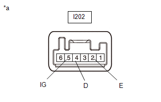
(2) Check the indicator light illuminates.
OK:
|
Auxiliary Battery Connection |
Specified Condition |
|---|---|
|
Auxiliary battery positive (+) → I202-5 (IG) Auxiliary battery negative (-) → I202-4 (D) |
Illuminates |
If the result is not as specified, replace the front wiper deicer switch.
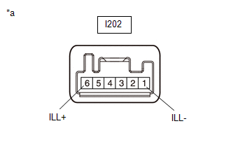
(b) Check the illumination.
| (1) Apply auxiliary battery voltage to the connector and check the illumination conditions. OK:
If the result is not as specified, replace the front wiper deicer switch. |
|
Installation
INSTALLATION
CAUTION / NOTICE / HINT
COMPONENTS (INSTALLATION)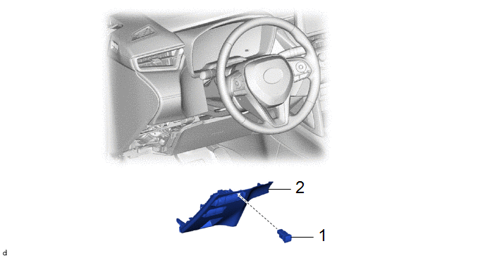
|
Procedure | Part Name Code |
.png) |
.png) |
 |
|---|---|---|---|---|---|
|
1 | FRONT WIPER DEICER SWITCH |
84794A | - |
- | - |
|
2 | LOWER NO.1 INSTRUMENT PANEL FINISH PANEL |
55432D | - |
- | - |
PROCEDURE
1. INSTALL FRONT WIPER DEICER SWITCH
2. INSTALL LOWER NO.1 INSTRUMENT PANEL FINISH PANEL
Click here .gif)


