Toyota Corolla Cross: Vanity Light
Removal
REMOVAL
CAUTION / NOTICE / HINT
COMPONENTS (REMOVAL)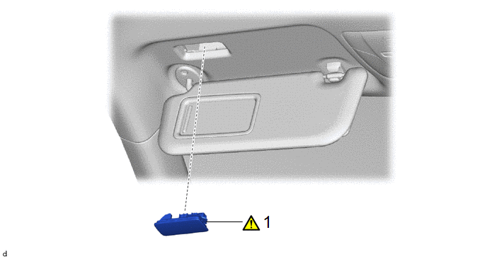
|
Procedure | Part Name Code |
.png) |
.png) |
 |
|---|---|---|---|---|---|
|
1 | VANITY LIGHT ASSEMBLY |
81340 |
|
- | - |
.gif)
CAUTION / NOTICE / HINT
HINT:
- Use the same procedure for the RH side and LH side.
- The following procedure is for the LH side.
PROCEDURE
1. REMOVE VANITY LIGHT ASSEMBLY
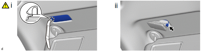
(1) Using a moulding remover A, disengage the claw to remove the vanity light assembly.
(2) Disconnect the connector.
Inspection
INSPECTION
PROCEDURE
1. INSPECT VANITY LIGHT ASSEMBLY (for LH Side)
(a) Check the illumination.
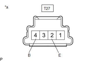
| (1) Apply auxiliary battery voltage to the vanity light assembly and check that the lights illuminate. OK:
If the result is not as specified, replace the vanity light assembly. |
|
2. INSPECT VANITY LIGHT ASSEMBLY (for RH Side)
(a) Check the illumination.
| (1) Apply auxiliary battery voltage to the vanity light assembly and check that the lights illuminate. OK:
If the result is not as specified, replace the vanity light assembly. |
|

Installation
INSTALLATION
CAUTION / NOTICE / HINT
COMPONENTS (INSTALLATION)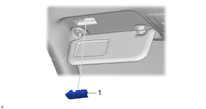
|
Procedure | Part Name Code |
.png) |
.png) |
 |
|---|---|---|---|---|---|
|
1 | VANITY LIGHT ASSEMBLY |
81340 | - |
- | - |
CAUTION / NOTICE / HINT
HINT:
- Use the same procedure for the RH side and LH side.
- The following procedure is for the LH side.
PROCEDURE
1. INSTALL VANITY LIGHT ASSEMBLY


