Toyota Corolla Cross: Vanity Light Switch
Inspection
INSPECTION
PROCEDURE
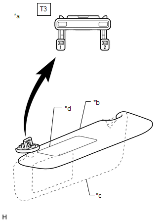
1. INSPECT VANITY LIGHT SWITCH LH (VISOR ASSEMBLY LH)
(a) Check the resistance.
| (1) Measure the resistance according to the value(s) in the table below.
Standard Resistance: |
Tester Connection | Condition |
Specified Condition | |
T3-1 - T3-2 | Visor up |
10 kΩ or higher | |
T3-1 - T3-2 | Mirror cover fully closed with visor down |
10 kΩ or higher | |
T3-1 - T3-2 | Mirror cover fully open with visor down |
Below 1 Ω | If the result is not as specified, replace the vanity light switch LH (visor assembly LH). |
 |
|
*a | Component without harness connected
(Vanity Light Switch LH (Visor Assembly LH)) | |
*b | Visor up | |
*c | Visor down | |
*d | Mirror Cover | | |
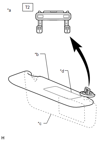
2. INSPECT VANITY LIGHT SWITCH RH (VISOR ASSEMBLY RH)
(a) Check the resistance.
| (1) Measure the resistance according to the value(s) in the table below.
Standard Resistance: |
Tester Connection | Condition |
Specified Condition | |
T2-1 - T2-2 | Visor up |
10 kΩ or higher | |
T2-1 - T2-2 | Mirror cover fully closed with visor down |
10 kΩ or higher | |
T2-1 - T2-2 | Mirror cover fully open with visor down |
Below 1 Ω | If the result is not as specified, replace the vanity light switch RH (visor assembly RH). |
 |
|
*a | Component without harness connected
(Vanity Light Switch RH (Visor Assembly RH)) | |
*b | Visor up | |
*c | Visor down | |
*d | Mirror Cover | | |
Installation
INSTALLATION
CAUTION / NOTICE / HINT
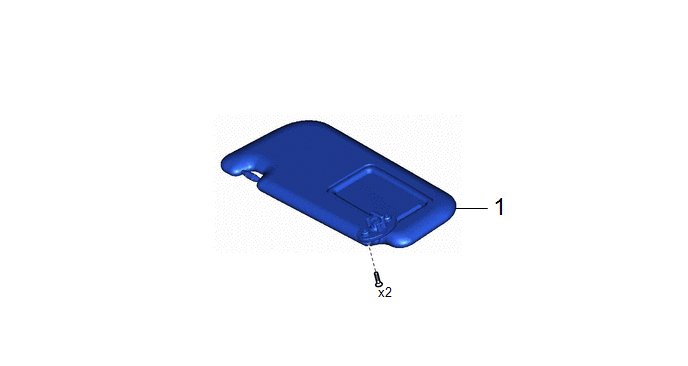
COMPONENTS (INSTALLATION)
|
Procedure | Part Name Code |
.png) |
.png) |
.png) |
|
1 | VANITY LIGHT SWITCH (VISOR ASSEMBLY) |
74320 | - |
- | - |
CAUTION / NOTICE / HINT
HINT:
- Use the same procedure for the RH side and LH side.
- The following procedure is for the LH side.
PROCEDURE
1. INSTALL VANITY LIGHT SWITCH (VISOR ASSEMBLY)
READ NEXT:
REMOVAL CAUTION / NOTICE / HINT COMPONENTS (REMOVAL)
Procedure Part Name Code
1 PRECAUTION
-
- -
2 DISCONNECT CABLE FROM NEGATIV
SEE MORE:
INSTALLATION
CAUTION / NOTICE / HINT
Procedure
Part Name Code
1
TEMPORARILY TIGHTEN REAR NO. 1 SUSPENSION ARM ASSEMBLY
48720A
-
-
2
TEMPORARILY T
INITIALIZATION
NOTICE:
Initialization can be confirmed through the tire pressure warning light.
If the ignition switch is turned off during initialization, the tire pressure
warning ECU and receiver memorizes that initialization was being performed.
Therefore, it is not necessary to


