Toyota Corolla Cross: Vacuum Sensor
Removal
REMOVAL
CAUTION / NOTICE / HINT
COMPONENTS (REMOVAL)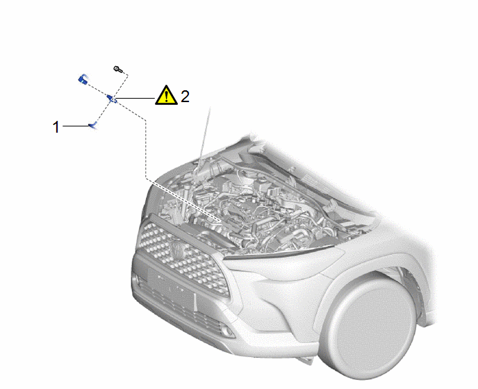
|
Procedure | Part Name Code |
.png) |
.png) |
 |
|---|---|---|---|---|---|
|
1 | VACUUM HOSE |
- | - |
- | - |
|
2 | E.F.I. VACUUM SENSOR ASSEMBLY (MANIFOLD ABSOLUTE PRESSURE SENSOR) |
89421 |
|
- | - |
CAUTION / NOTICE / HINT
NOTICE:
This procedure includes the removal of small-head bolts. Refer to Small-Head Bolts of Basic Repair Hint to identify the small-head bolts.
Click here .gif)
PROCEDURE
1. SEPARATE VACUUM HOSE

2. REMOVE E.F.I. VACUUM SENSOR ASSEMBLY (MANIFOLD ABSOLUTE PRESSURE SENSOR)
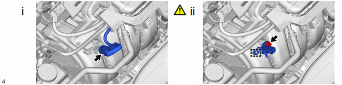
(1) Disconnect the E.F.I. vacuum sensor assembly (manifold absolute pressure sensor) connector.
(2) Using an 8 mm socket wrench, remove the bolt and E.F.I. vacuum sensor assembly (manifold absolute pressure sensor) from the intake manifold.
Installation
INSTALLATION
CAUTION / NOTICE / HINT
COMPONENTS (INSTALLATION)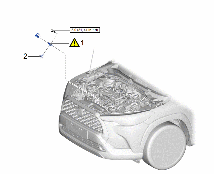
|
Procedure | Part Name Code |
.png) |
.png) |
 |
|---|---|---|---|---|---|
|
1 | E.F.I. VACUUM SENSOR ASSEMBLY (MANIFOLD ABSOLUTE PRESSURE SENSOR) |
89421 |
|
- | - |
|
2 | VACUUM HOSE |
- | - |
- | - |
.png) |
N*m (kgf*cm, ft.*lbf): Specified torque |
- | - |
CAUTION / NOTICE / HINT
NOTICE:
This procedure includes the installation of small-head bolts. Refer to Small-Head Bolts of Basic Repair Hint to identify the small-head bolts.
Click here .gif)
PROCEDURE
1. INSTALL E.F.I. VACUUM SENSOR ASSEMBLY (MANIFOLD ABSOLUTE PRESSURE SENSOR)
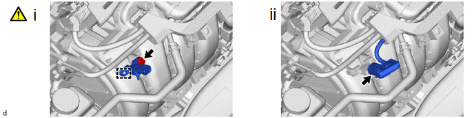
(1) Using an 8 mm socket wrench, install the E.F.I. vacuum sensor assembly (manifold absolute pressure sensor) to the intake manifold with the bolt.
Torque:
5.0 N·m {51 kgf·cm, 44 in·lbf}
(2) Connect the E.F.I. vacuum sensor assembly (manifold absolute pressure sensor) connector.
2. CONNECT VACUUM HOSE


