Toyota Corolla Cross: Removal
REMOVAL
CAUTION / NOTICE / HINT
COMPONENTS (REMOVAL)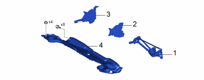
|
Procedure | Part Name Code |
.png) |
.png) |
 |
|---|---|---|---|---|---|
|
1 | WINDSHIELD WIPER MOTOR AND LINK ASSEMBLY |
- | - |
- | - |
|
2 | WATER GUARD PLATE |
55734D | - |
- | - |
|
3 | NO. 1 HEATER AIR DUCT SPLASH SHIELD SEAL |
55737B | - |
- | - |
|
4 | OUTER COWL TOP PANEL SUB-ASSEMBLY |
55701J | - |
- | - |
|
Procedure | Part Name Code |
|
|
| |
|---|---|---|---|---|---|
|
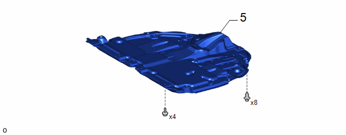
5 | NO. 1 ENGINE UNDER COVER ASSEMBLY |
51410 | - |
- | - |
|
Procedure | Part Name Code |
|
|
| |
|---|---|---|---|---|---|
|
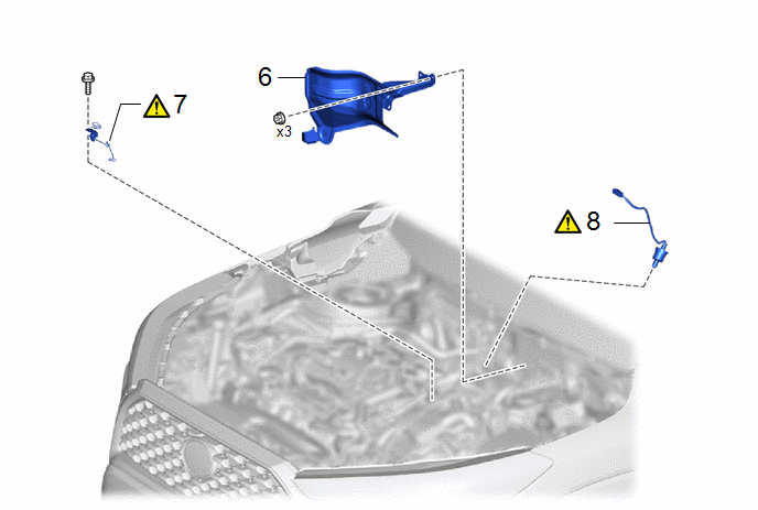
6 | REMOVE DASH PANEL HEAT INSULATOR |
55225C | - |
- | - |
|
7 | WIRE HARNESS CLAMP BRACKET |
- |
|
- | - |
|
8 | AIR FUEL RATIO SENSOR |
89467B |
|
- | - |
CAUTION / NOTICE / HINT
The necessary procedures (adjustment, calibration, initialization or registration) that must be performed after parts are removed and installed, or replaced during air fuel ratio sensor removal/installation are shown below.
Necessary Procedures After Parts Removed/Installed/Replaced|
Replaced Part or Performed Procedure |
Necessary Procedure | Effect/Inoperative Function when Necessary Procedure not Performed |
Link |
|---|---|---|---|
| Inspection After Repair |
|
|
PROCEDURE
1. REMOVE WINDSHIELD WIPER MOTOR AND LINK ASSEMBLY
Click here
.gif)
2. REMOVE WATER GUARD PLATE
Click here
3. REMOVE NO. 1 HEATER AIR DUCT SPLASH SHIELD SEAL
Click here
4. REMOVE OUTER COWL TOP PANEL SUB-ASSEMBLY
Click here
5. REMOVE NO. 1 ENGINE UNDER COVER ASSEMBLY
Click here
6. REMOVE DASH PANEL HEAT INSULATOR
7. REMOVE WIRE HARNESS CLAMP BRACKET
|
|
CAUTION: To prevent burns, do not touch the engine, exhaust manifold or other high temperature components while the engine is hot. .png) |
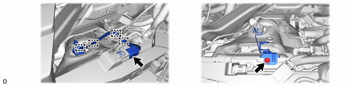
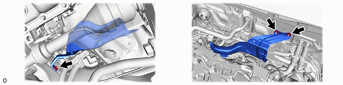
8. REMOVE AIR FUEL RATIO SENSOR
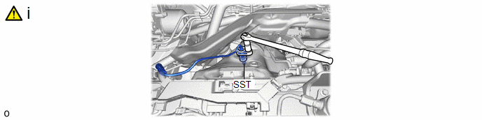
(1) Using SST, remove the air fuel ratio sensor from the exhaust manifold.
SST: 09224-00012
NOTICE:
If the air fuel ratio sensor has been struck or dropped, replace it.


