Toyota Corolla Cross: Installation
INSTALLATION
CAUTION / NOTICE / HINT
COMPONENTS (INSTALLATION)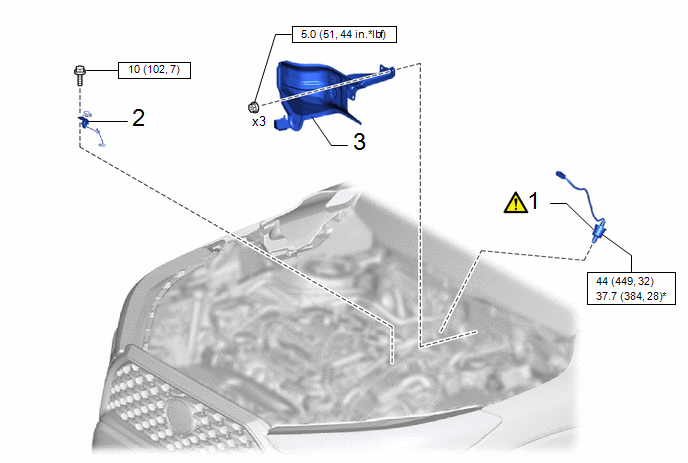
|
Procedure | Part Name Code |
.png) |
.png) |
 |
|---|---|---|---|---|---|
|
1 | AIR FUEL RATIO SENSOR |
89467B |
|
- | - |
|
2 | WIRE HARNESS CLAMP BRACKET |
- | - |
- | - |
|
3 | REMOVE DASH PANEL HEAT INSURATOR |
55225C | - |
- | - |
.png) |
N*m (kgf*cm, ft.*lbf): Specified torque |
* | For use with SST |
|
Procedure | Part Name Code |
|
|
| |
|---|---|---|---|---|---|
|
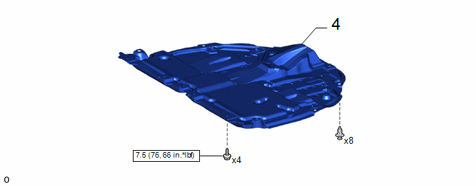
4 | NO. 1 ENGINE UNDER COVER ASSEMBLY |
51410 | - |
- | - |
|
|
N*m (kgf*cm, ft.*lbf): Specified torque |
- | - |
|
Procedure | Part Name Code |
|
|
| |
|---|---|---|---|---|---|
|
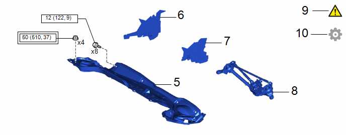
5 | OUTER COWL TOP PANEL SUB-ASSEMBLY |
55701J | - |
- | - |
|
6 | NO. 1 HEATER AIR DUCT SPLASH SHIELD SEAL |
55737B | - |
- | - |
|
7 | WATER GUARD PLATE |
55734D | - |
- | - |
|
8 | WINDSHIELD WIPER MOTOR AND LINK ASSEMBLY |
- | - |
- | - |
|
9 | INSPECT FOR EXHAUST GAS LEAK |
- |
|
- | - |
|
10 | PERFORM INITIALIZATION |
- | - |
- |
|
.png) |
Tightening torque for "Major areas involving basic vehicle performance such as moving/turning/stopping" : N*m (kgf*cm, ft.*lbf) |
|
N*m (kgf*cm, ft.*lbf): Specified torque |
PROCEDURE
1. INSTALL AIR FUEL RATIO SENSOR
|
|
HINT: Perform "Inspection After Repair" after replacing the air fuel ratio sensor. Click here |
.png)
|
*a | Torque Wrench Fulcrum Length |
- | - |
(1) Using SST, install the air fuel ratio sensor to the exhaust manifold.
SST: 09224-00012
Torque:
Specified tightening torque :
44 N·m {449 kgf·cm, 32 ft·lbf}
NOTICE:
If the air fuel ratio sensor has been struck or dropped, replace it.
HINT:
- Calculate the torque wrench reading when changing the fulcrum length of the torque wrench.
Click here
.gif)
- When using SST (fulcrum length of 30 mm (1.18 in.)) + torque wrench (fulcrum length of 180 mm (7.09 in.)):
37.7 N*m (384 kgf*cm, 28 ft.*lbf)
2. INSTALL WIRE HARNESS CLAMP BRACKET
Torque:
10 N·m {102 kgf·cm, 7 ft·lbf}
3. INSTALL DASH PANEL HEAT INSULATOR
Torque:
5.0 N·m {51 kgf·cm, 44 in·lbf}
4. INSTALL NO. 1 ENGINE UNDER COVER ASSEMBLY
Click here
5. INSTALL OUTER COWL TOP PANEL SUB-ASSEMBLY
Click here
6. INSTALL NO. 1 HEATER AIR DUCT SPLASH SHIELD SEAL
Click here
7. INSTALL WATER GUARD PLATE
8. INSTALL WINDSHIELD WIPER MOTOR AND LINK ASSEMBLY
Click here
9. INSPECT FOR EXHAUST GAS LEAK
|
|
Click here |
10. PERFORM INITIALIZATION
(a) Perform "Inspection After Repair" after replacing the air fuel ratio sensor.
Click here


