Toyota Corolla Cross Owners & Service Manuals

Toyota Corolla Cross: Terminals Of Ecu

TERMINALS OF ECU

CHECK TIRE PRESSURE WARNING ECU AND RECEIVER
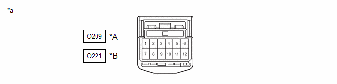
*A

w/ Smart Key System

*B

w/o Smart Key System

*a

Front view of wire harness connector

(to Tire Pressure Warning ECU and Receiver)

-

-

(a) Disconnect the O209*1 or O221*2 tire pressure warning ECU and receiver connector and measure the voltage or resistance on the wire harness side.

  • *1: w/ Smart Key System
  • *2: w/o Smart Key System
w/ Smart Key System

Terminal No. (Symbol)

Terminal Description

Condition

Specified Condition

O209-1 (IGR) - O209-12 (GND)

IG power source

Ignition switch ON

10 to 16 V

O209-7 (+B) - O209-12 (GND)

Power supply (from auxiliary battery)

Always

10 to 16 V

O209-9 (CANH) - O209-10 (CANL)

CAN communication line

Ignition switch off

54 to 69 Ω

O209-12 (GND) - Body ground

Ground

Always

Below 1 Ω

w/o Smart Key System

Terminal No. (Symbol)

Terminal Description

Condition

Specified Condition

O221-1 (IGR) - O221-12 (GND)

IG power source

Ignition switch ON

10 to 16 V

O221-7 (+B) - O221-12 (GND)

Power supply (from auxiliary battery)

Always

10 to 16 V

O221-9 (CANH) - O221-10 (CANL)

CAN communication line

Ignition switch off

54 to 69 Ω

O221-12 (GND) - Body ground

Ground

Always

Below 1 Ω

    READ NEXT:

     Diagnosis System

    DIAGNOSIS SYSTEM CHECK WARNING LIGHT NOTICE: When there is a problem with the tire pressure warning system, the tire pressure warning light blinks at 0.5 second intervals, and illuminates aft

     Freeze Frame Data

    FREEZE FRAME DATA FREEZE FRAME DATA HINT: When a DTC is stored, the freeze frame data stores the current vehicle (sensor) state. The freeze frame data cannot be cleared or updated until th

     Fail-safe Chart

    FAIL-SAFE CHART FAIL-SAFE FUNCTION (a) When a malfunction occurs in the tire pressure warning system, the tire pressure warning light illuminates after blinking for 1 minute to inform the driver o

    SEE MORE:

     Front Right Air Mix Damper Control Servo Motor Actuator Stuck Off (B145B7F)

    DESCRIPTION The No. 1 air conditioning radiator damper servo sub-assembly sends pulse signals to inform the air conditioning amplifier assembly of the damper position. The air conditioning amplifier assembly activates the motor (normal or reverse) based on these signals to move the air outlet damper

     Removal

    REMOVAL CAUTION / NOTICE / HINT COMPONENTS (REMOVAL) Procedure Part Name Code 1 DRIVE SHAFT BEARING BRACKET 43457 - - - 2 V-RIBBED BELT TENSIONER ASSEMBLY 16620D - - - 3 NO. 2 RADIATOR HOSE 16572D -

    © 2020-2025 Copyright www.tcorollacross.com PT NL