Toyota Corolla Cross: Terminals Of Ecu
TERMINALS OF ECU
CHECK 4WD ECU ASSEMBLY
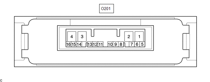
(a) Measure the voltage and resistance of the connector.
|
Terminal No. (Symbol) |
Terminal Description |
Condition |
Specified Condition |
|---|---|---|---|
|
O201-6 (CANH) - O201-5 (CANL) |
CAN communication line |
Cable disconnected from negative (-) auxiliary battery terminal |
54 to 69 Ω |
|
O201-4 (GND) - Body ground |
Ground |
Always |
Below 1 Ω |
|
O201-3 (IG1) - O201-4 (GND) |
Power source voltage |
Ignition switch ON |
11 to 14 V |
|
O201-2 (SLC+) - O201-1 (SLC-) |
4WD linear solenoid signal |
D position, engine idling |
Pulse generation (See waveform 1) |
If the result is not as specified, the 4WD ECU assembly may have a malfunction.
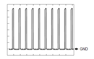
(b) Using an oscilloscope, check the waveform 1.
Waveform 1 (Reference)|
Item |
Content |
|---|---|
|
Terminal No. (Symbol) |
O201-2 (SLC+) - O201-1 (SLC-) |
|
Tester Range |
2 V/DIV., 1 msec./DIV. |
|
Condition |
D position, Idling |