Toyota Corolla Cross: Removal
REMOVAL
CAUTION / NOTICE / HINT
COMPONENTS (REMOVAL)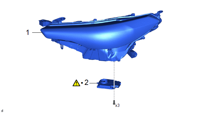
|
Procedure | Part Name Code |
.png) |
.png) |
 |
|---|---|---|---|---|---|
|
1 | HEADLIGHT ASSEMBLY |
- | - |
- | - |
|
2 | HEADLIGHT ECU SUB-ASSEMBLY |
- |
|
- | - |
|
*1 | HEADLIGHT UNIT ASSEMBLY |
- | - |
|
● | Non-reusable part |
- | - |
CAUTION / NOTICE / HINT
The necessary procedures (adjustment, calibration, initialization or registration) that must be performed after parts are removed and installed, or replaced during headlight ECU sub-assembly removal/installation are shown below.
Necessary Procedure After Parts Removed/Installed/Replaced|
Replaced Part or Performed Procedure |
Necessary Procedure | Effect/Inoperative Function When Necessary Procedures are not Performed |
Link |
|---|---|---|---|
| Headlight ECU sub-assembly LH |
| Automatic headlight beam level control system |
|
HINT:
- Use the same procedure for the RH side and LH side.
- The following procedure is for the LH side.
PROCEDURE
1. REMOVE HEADLIGHT ASSEMBLY
Click here
.gif)
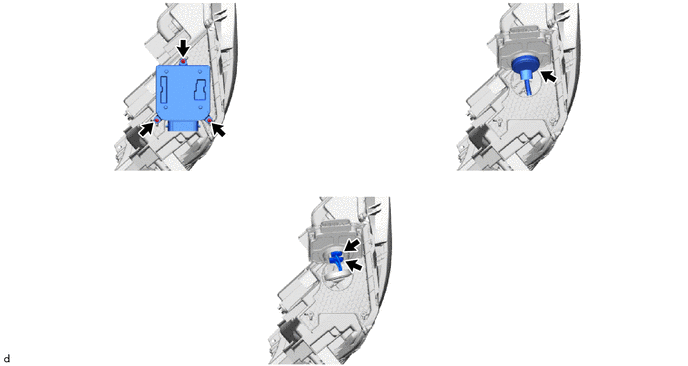
2. REMOVE HEADLIGHT ECU SUB-ASSEMBLY
|
|
NOTICE: Make sure to replace the headlight ECU sub-assembly with a new one. Failure to do so may cause water ingress. |
SST: 09890-47010
09891-04010
09891-04020
09891-04030
09891-04040