Toyota Corolla Cross: Removal
REMOVAL
CAUTION / NOTICE / HINT
COMPONENTS (REMOVAL)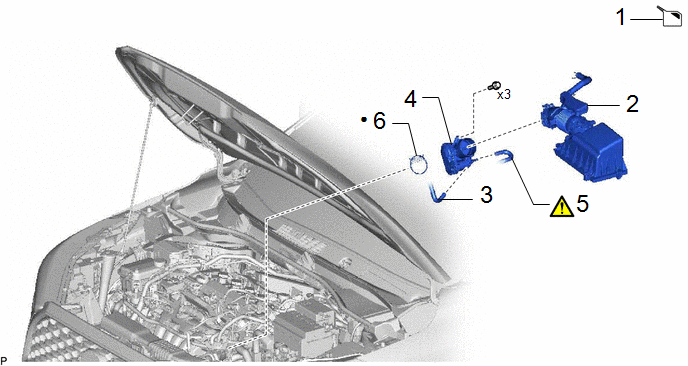
|
Procedure | Part Name Code |
.png) |
.png) |
 |
|---|---|---|---|---|---|
|
1 | DRAIN ENGINE COOLANT |
- | - |
|
- |
| 2 |
AIR CLEANER CAP WITH AIR CLEANER HOSE |
- | - |
- | - |
|
3 | NO. 8 WATER BY-PASS HOSE |
16296 | - |
- | - |
|
4 | THROTTLE BODY WITH MOTOR ASSEMBLY |
22030 | - |
- | - |
|
5 | NO. 5 WATER BY-PASS HOSE |
- |
|
- | - |
|
6 | THROTTLE BODY GASKET |
22271 | - |
- | - |
|
● | Non-reusable part |
- | - |
CAUTION / NOTICE / HINT
The necessary procedures (adjustment, calibration, initialization or registration) that must be performed after parts are removed and installed, or replaced during throttle body with motor assembly removal/installation are shown below.
Necessary Procedures After Parts Removed/Installed/Replaced|
Replaced Part or Performed Procedure |
Necessary Procedure | Effect/Inoperative Function when Necessary Procedure not Performed |
Link |
|---|---|---|---|
| Inspection after repair |
|
|
NOTICE:
This procedure includes the removal of small-head bolts. Refer to Small-Head Bolts of Basic Repair Hint to identify the small-head bolts.
Click here .gif)
PROCEDURE
1. DRAIN ENGINE COOLANT
Click here
2. REMOVE AIR CLEANER CAP WITH AIR CLEANER HOSE
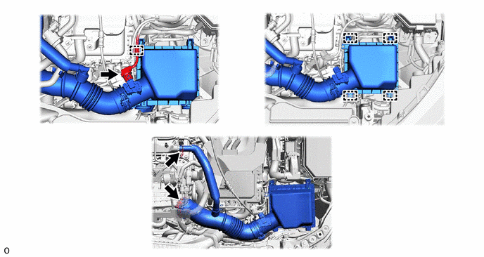
3. DISCONNECT NO.8 WATER BY-PASS HOSE

4. REMOVE THROTTLE BODY WITH MOTOR ASSEMBLY

5. DISCONNECT NO. 5 WATER BY-PASS HOSE
|
|
NOTICE: If the throttle body with motor assembly has been struck or dropped, replace it. |

6. REMOVE THROTTLE BODY GASKET